Maker Pro
Maker Pro

Help on Samsung Syncmaster 732N led conversion

mikey5791

Jun 7, 2013
174
Joined
Jun 7, 2013
Messages
174
Hi,
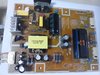
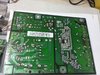
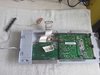
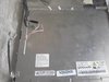
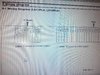
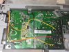
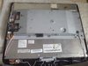
Yesterday i received this lcd monitor free but the owner says the backlight doesn't work anymore. I removed the metal case and tested the main and power board on an acer lcd monitor and the lcd display comes out fine, meaning the power board and inverter still in working condition. Now my plan is to replace the old non working ccfl tubes(upper 2 tubes and bottom monitor 2 tubes) to led bulb. I saw some online china seller selling led conversion kit but i couldn't get any info on the led by asking those seller. I wonder if those led are bright enough to light my monitor screen. Here is the link
https://shopee.com.my/355mm-LED-Back...869.6210934918

Btw, the led driver board has four pin out with color of red, yellow, yellow and black. Has anyone done these type of led conversion and kind enough to point out on which part of the power board i need to connect all the four pin out.
My guess is the red pin out is for positive 12vdc, black pin out is the ground negative.
Hope someone can share or suggest their knowledge to help me complete this project.
Thanking in advance.
 

Attachments

  • IMG_20200923_092332.jpg
    IMG_20200923_092332.jpg
    266.7 KB · Views: 4
  • IMG_20200923_092212.jpg
    IMG_20200923_092212.jpg
    322.8 KB · Views: 4
  • IMG_20200923_090351.jpg
    IMG_20200923_090351.jpg
    310.7 KB · Views: 4
  • IMG_20200923_090024.jpg
    IMG_20200923_090024.jpg
    176.6 KB · Views: 4

Bluejets

Oct 5, 2014
6,920
Joined
Oct 5, 2014
Messages
6,920
Done it on a Syncmaster P2350 ....so long ago I don't remember much about it.
Still going strong.....
Removed the cfl tubes from the hv drivers and picked up a 12v source on the board somewhere from memory.
This was of course and the LED and driver pack suitable for this model monitor.
Might be better to find some that suits your model rather than a "fits-all".

BTW,,,all it takes to verify the backlights are out is to shine a torch at an angle to the screen on power up. You'll see the image....o_Oo_O

For fitting, there are hordes of videos on youtube.
 

mikey5791

Jun 7, 2013
174
Joined
Jun 7, 2013
Messages
174
Appreciate your input Bluejets. I will check on some youtube for the fitting.
 

Bluejets

Oct 5, 2014
6,920
Joined
Oct 5, 2014
Messages
6,920
You will have to download the manual and place the page here.
I'm not about to download from who knows where.
As for wrong connections, that depends on what exactly you mean.
 

mikey5791

Jun 7, 2013
174
Joined
Jun 7, 2013
Messages
174
As attached page 74 downloaded from the said manual on the wiring diagram.
 

Attachments

  • IMG_20200926_222453.jpg
    IMG_20200926_222453.jpg
    477.4 KB · Views: 3

bertus

Moderator
Nov 8, 2019
3,321
Joined
Nov 8, 2019
Messages
3,321
Hello,

Do you mean the connections of the IP board:

IP_board samsung.png

This is just a screenshot of the manual page.
It is much better readable as a photo taken from the screen with all the moire on it.

When using win10, you could use the snipping tool.
I am using a linux system, that allows to export a screenshot to a paintlike porgram.
I used KolourPaint to cut out the portion of interest.

Bertus
 

mikey5791

Jun 7, 2013
174
Joined
Jun 7, 2013
Messages
174
bertus,
Yes, the IP board is what i wish to display. Fyi i plan to solder pin 2 to red VIN side of led driver for the 14vdc source, while pin 9 to first yellow ENA side of led driver for the on off function. The second yellow DIM of led driver should be soldered to pin 8(B dim). The black wire of led driver can be soldered to any grounded screw on chassis.
Are the above planned wiring correctly set up for the yet to buy led driver conversion kit ?
The seller is either not conversant or reply my questions on the wiring. I hope anyone with past experience on the led conversion can shed some comments, hints, suggestions or improve the setup. Thank you all for the patience and kind replies. I do appreciate very much.
 

bertus

Moderator
Nov 8, 2019
3,321
Joined
Nov 8, 2019
Messages
3,321
Hello,

On page 59 I found this description of the signals on the IP connector:

Inverter control.png

Bertus
 

mikey5791

Jun 7, 2013
174
Joined
Jun 7, 2013
Messages
174
Bertus,
So it looks like the second yellow wire should solder to pin 1( instead of pin 8 which is a fixed type dimming). Thanks for pointing out page 59 on those ip signals.
 

mikey5791

Jun 7, 2013
174
Joined
Jun 7, 2013
Messages
174
Fyi, i had placed order for the led conversion kit.
Due to the current pandemic situation, it will arrive at my door step in 1-2 months time.
After the kit installation, I will post an update on the result here.
Many thanks for the kind assistance.
 

mikey5791

Jun 7, 2013
174
Joined
Jun 7, 2013
Messages
174
Bluejets and bertus,
Received the led conversion kit yesterday and fitted the wiring as suggested here.
Voila! It works! To be honest, I am quite satisfied with the led quality and brightness is adjustable.
Hope it will continue to work for many years to come. My sincere thanks for your generous advice and kind assistance.
 

Attachments

  • IMG_20201008_075246.jpg
    IMG_20201008_075246.jpg
    193.7 KB · Views: 3
  • IMG_20201008_065459.jpg
    IMG_20201008_065459.jpg
    260.1 KB · Views: 3
  • IMG_20201008_073246.jpg
    IMG_20201008_073246.jpg
    208.6 KB · Views: 2
Top