Maker Pro
Maker Pro

Help to reduce this schematic price (beginner)

Gediminas

Nov 24, 2015
22
Joined
Nov 24, 2015
Messages
22
Hello,
please give me some advice in how to reduce price for this crossover I designed.

First, a little background. I am completely new to electronics, but while ago I had little free time and started building sub-woofer, was not planning anything difficult, but during process I got more and more complicated (and interesting). With help of few members of this community (very big thanks to: Gryd3, dorke and BobK) I got some basic knowledge and understanding which I used to put this schematic up.
kolonele naujausia.png
Components list:
Inductors Capacitors
L1 19.1mH C1 66.31 uF
L2 19.1mH C2 198.94 uF
L3 6.37mH C3 265.25 uF
L4 0.32mH C4 4.42 uF
L5 1.91mH C5 13.26 uF
L6 0.42mH C6 4.42 uF

Problem is that then I showed it in my local electronic components store, they told me that it would be approximately around 150 euros to build. That is way to much for me to pay, especially keeping in my that it is my first project...

As far as I understand, this enormous price adds up because they don't have anything close to first 3 inductors I need, I can order them, but they will cost around 130 euros. And that is only for first 3 components needed...

In my understanding to overcome this problem I need to change something in my schematic or find cheaper alternative.

I searched ebay and found this: http://www.ebay.co.uk/itm/2x-Radial...hash=item3ce2de63c2:m:m6qvxQQR6OL0UyPrXrgtQLA
Are they suitable for my diagram?

Also are these conductor suitable either? http://www.ebay.co.uk/itm/Radial-Al...hash=item3ccf1025cc:m:m5IwVRuQT_FhEXMv28sOJTQ

Any help appreciated
 

Gryd3

Jun 25, 2014
4,098
Joined
Jun 25, 2014
Messages
4,098
Hello,
please give me some advice in how to reduce price for this crossover I designed.

First, a little background. I am completely new to electronics, but while ago I had little free time and started building sub-woofer, was not planning anything difficult, but during process I got more and more complicated (and interesting). With help of few members of this community (very big thanks to: Gryd3, dorke and BobK) I got some basic knowledge and understanding which I used to put this schematic up.
View attachment 25497
Components list:
Inductors Capacitors
L1 19.1mH C1 66.31 uF
L2 19.1mH C2 198.94 uF
L3 6.37mH C3 265.25 uF
L4 0.32mH C4 4.42 uF
L5 1.91mH C5 13.26 uF
L6 0.42mH C6 4.42 uF

Problem is that then I showed it in my local electronic components store, they told me that it would be approximately around 150 euros to build. That is way to much for me to pay, especially keeping in my that it is my first project...

As far as I understand, this enormous price adds up because they don't have anything close to first 3 inductors I need, I can order them, but they will cost around 130 euros. And that is only for first 3 components needed...

In my understanding to overcome this problem I need to change something in my schematic or find cheaper alternative.

I searched ebay and found this: http://www.ebay.co.uk/itm/2x-Radial...hash=item3ce2de63c2:m:m6qvxQQR6OL0UyPrXrgtQLA
Are they suitable for my diagram?

Also are these conductor suitable either? http://www.ebay.co.uk/itm/Radial-Al...hash=item3ccf1025cc:m:m5IwVRuQT_FhEXMv28sOJTQ

Any help appreciated
I can only think of either reducing part-count by using 1st order filters instead of 2nd order, or change the low-pass cut-off frequency to use a part that the shop may have on-hand or for less money.
 

Gediminas

Nov 24, 2015
22
Joined
Nov 24, 2015
Messages
22
And what about inductors I found on ebay? They are not suitable for audio system?
 

Alec_t

Jul 7, 2015
3,590
Joined
Jul 7, 2015
Messages
3,590
Those inductors would handle only tiny currents; not the big currents you would need for driving speaker loads of 8 or 16 Ohms.
 

BobK

Jan 5, 2010
7,682
Joined
Jan 5, 2010
Messages
7,682
I agree with gryd3 to go to a first order filter rather than second order. Not only for cost, but the components are less critical and it is likely to work better than a second order design unless you really know what you are doing.

To save money, make your own inductors. They are nothing more than a coil of wire of a specific size and number of turns. You can find online calculators for this. Air core inductors are often used for crossovers because they avoid some problems with ferromagnetic materials. But they will be large.

Also, non-polarized capacitors in the microfarad range are expensive, but you can make your own by using two polarized ones of twice the value and connecting them back to back, i.e. connect the two negative terminals together and then the 2 positive terminals make a polarized capacitor of half the value.

Bob
 

Gediminas

Nov 24, 2015
22
Joined
Nov 24, 2015
Messages
22
Thank You for great advise,
Now I am planning for recalculating everything for first order filters, but the main reason I choose this kind in the first place was to keep my amplifier impedance drop below 8Ω, my reasoning was that this kind of filter cut frequency faster so less time signal will be overlaped. Was I worrying about without any reason and I can change everything to first order? Or should I leave tweeter filter as it is since its components are for more or less affordable price.
 

Gryd3

Jun 25, 2014
4,098
Joined
Jun 25, 2014
Messages
4,098
Thank You for great advise,
Now I am planning for recalculating everything for first order filters, but the main reason I choose this kind in the first place was to keep my amplifier impedance drop below 8Ω, my reasoning was that this kind of filter cut frequency faster so less time signal will be overlaped. Was I worrying about without any reason and I can change everything to first order? Or should I leave tweeter filter as it is since its components are for more or less affordable price.
n160fig5.png

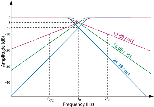
The overlap is not as large as you would expect...
The Cross-over or Cut-off frequency is calculated/measured when the signal to the speaker hits -3dB which is considered 'half-power'...
So... if the mid and sub both cross-over at the same frequency, the both will overlap, but each one will be at half-power. (Both together would equal a full load)
There is great deal of overlap above and below the frequency, but the power is so low it will be hard to hear, and will be negligible.
 

Gediminas

Nov 24, 2015
22
Joined
Nov 24, 2015
Messages
22
Thank You for simple explanation, I saw similar diagram before in other sites, but it was never explained well. This solved one my of the biggest doubts.
 

BobK

Jan 5, 2010
7,682
Joined
Jan 5, 2010
Messages
7,682
This is why I said the 2nd order filter is more critical, it is harder to get the overlap right when the slope is steeper.

Bob
 
Top