Unlaced8126
- Feb 25, 2023
- 3
- Joined
- Feb 25, 2023
- Messages
- 3
I want to attempt upgrading the soldered RAM on my HP 13-ay0095AU from 8GB to 16GB. While I have the tools and experience soldering, I am having some trouble understanding the documentation (schematics .PDF and .cad file attached).
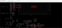
As far as I can tell, they should be the correct and the same board. RAM-related info seems to be mainly on page 12 of the PDF. I've also attached a photo of the physical board, found online.
I have a few questions:
1. The board seems to physically have 8 spots for RAM chips. However, Googling the part numbers for the 8 GB setups (e.g. H5AN8G6NCJR-XNC) suggests that those are 16x 512 MB chips? Am I reading this wrongly?
2. If I find an online vendor with the part "K4AAG165WA-BCWE", do I just order 1 unit? Or 8 units, 1 for each spot?
3. How do the "RAM_ID1...4" work? Are they just bridged pads or resistors or something else?
Any help/tips/advice would be greatly appreciated!


