Maker Pro
Maker Pro

help with a transistor?

corvairbob

Jun 14, 2022
12
Joined
Jun 14, 2022
Messages
12
i have a traffic light on my garage for a ornamint. i was messing around trying to get the walk sign to work along with the light to see if i could get them to sequence. well i managed to burn out one of the output transisters. what i think it is, is a triac. as it has the heat sink body. but it has no number as the builder scracthed them off so people could not copy his work. the unit is 120 vac and has some IC'S on it and the output powers 120 bulbs. i think it is not fussy for bulbs as i have a regular bulb an led and florescent in the system. when i was messing around i connect a diode to it to get the don't walk light to be on during the yellow and red sequences of the traffic light. and i managed to burn the traces going to the yellow light. so i soldered in some 24 ga solid wire to rebuild the traces and got it to operate and found the yellow now stays one. so i must have fried that output if it is a triac. i can send a photo if anyone want to get an idea of what i'm working with.
thanks
 

Harald Kapp

Moderator
Moderator
Nov 17, 2011
13,722
Joined
Nov 17, 2011
Messages
13,722
i managed to burn out one of the output transisters. what i think it is, is a triac
So what? Transistor or Triac?
as it has the heat sink body
That is not much help. Many different types of components have cases meant to be attached to a heat sink.
i can send a photo
Please do. Size < 300 kB, otherwise you may get an error when uploading.
it has no number as the builder scracthed them off
That is going to be hard. No number, no component ID.
Do you have a model number of the traffic light?
 

corvairbob

Jun 14, 2022
12
Joined
Jun 14, 2022
Messages
12
thanks this is an aftermarket controller it is kind of like the ones the model rail road builders use. but the output must have been updated for 120vac output and input. i will ge a photo of it and maybe some can help. i can guess but then i have to mess around until i figure it out. here is the part there are 3 on the board. and if i can get the complete board and the back side. there is not much on the back but traces i had to crop out some of the bottom if needed i will crop out the top and you can imagine it together


IMG_20220615_084615.jpg IMG_20220615_084642.jpg IMG_20220615_084626.jpg
 

corvairbob

Jun 14, 2022
12
Joined
Jun 14, 2022
Messages
12
ok i went a tested the outputs while the system was powered up this is what i got

if you look at the close up photo the left and the right pins have 120 vac on them and the center one goes to 120vac thru a resistor and some type of ic module. and that one is also connected to the bulb looking at the back side you can see the main buss is the red wire then to the right of the triacs if they are triacs and the left side goes down to another module that is white

all the components? have the numbers rubbed off but the triac's outputs have some numbers at the bottom on the left i see c3 then the part has a dot and then the number 44 on them i do not understand why i get 120vac on both outside pins and then the center pin that goes thru the resistor and on to the light. is 120vac .

so it kind of looks like the gate is 120vac as well? i wonder this if you look at the back of the board you see the center pin going to the lights those 3 wires at the top are the lights. and the left pin drops down to the module and the right pin goes to the power input from the mains. l1 power and l2 neutral ? so maybe that left pin that goes down to the module is powering the module? anyway it kind of looks like i may be able to get a trais with the gate trigger at 120vac and 2 amps should be large enough

or would that configuration just be a power output transistor?

one more thing when i measured the light that remains on all 3 pins are powered so it could be possible the output is good and that white module that triggers the output is fused closed and is triggering the output?

any ideas thanks.
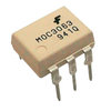
this is what i found online it has 120 volts Simplifies Logic Control of 115/240 Vac Power this is also used for Lighting Controls so now i winder if this burned and is causing the issue. i may ebay it and if you think the outputs are power transistors and not triacs? let me know thanks.
https://www.electronicscomp.com/moc3063-zero-cross-triac-optoisolator-ic
IMG_20220615_084626-1.jpg moc3063-zero-cross-triac-optoisolator-ic-800x800.jpg
this triac ic module has this for the description so that almost makes me thing the outputs are triacs as well
The MOC3063 devices consist of gallium arsenide infrared emitting diodes optically coupled to monolithic silicon detectors performing the functions of Zero Voltage Crossing bilateral triac drivers. They are designed for use with a triac in the interface of logic systems to equipment powered from 115/240 Vac lines, such as solid–state relays, industrial controls, motors, solenoids and consumer appliances,etc.
 
Last edited:

Harald Kapp

Moderator
Moderator
Nov 17, 2011
13,722
Joined
Nov 17, 2011
Messages
13,722
You are verylikely right that this is a triac or a thyristor (SCR). But in the absence of more information it is not practical to say which one could be a suitable replacement.
The board doesn't even look like a professionally made one, more like a homebrew pcb. Unless you know who built this or which schematic was used to build this, I'm afraid you are lost. At least I am.
 

corvairbob

Jun 14, 2022
12
Joined
Jun 14, 2022
Messages
12
i think i found out the black standing device is the to-220 and a bta08-400 device and the white flat id type device is the moc3021 device and this is the pin out for it a guy on another electronic site posted this one for me to use. thanks
upload_2022-6-17_8-5-12.png
 

Harald Kapp

Moderator
Moderator
Nov 17, 2011
13,722
Joined
Nov 17, 2011
Messages
13,722
Glad you found the schematic. Now all you need is the replacements parts.
 

corvairbob

Jun 14, 2022
12
Joined
Jun 14, 2022
Messages
12
i have some on order now from ebay some moc3021 ic modules and some bta08-400 triac modules. so they should be here next month and i will install them and see if they work. the worst case is they will fail and then all i can say if thanks for help and i tried. being this is an old board and built rather cheaply i guess it is the best anyone can do. if it fails i can get a complete unit for 30$ but i just want to see if i can fix this one.
thanks
 

ramussons

Jun 10, 2014
464
Joined
Jun 10, 2014
Messages
464
i think i found out the black standing device is the to-220 and a bta08-400 device and the white flat id type device is the moc3021 device and this is the pin out for it a guy on another electronic site posted this one for me to use. thanks
View attachment 55449
Is'nt there to be another resistor between G and A1 to protect against random triggering?
 

corvairbob

Jun 14, 2022
12
Joined
Jun 14, 2022
Messages
12
the diagram posted show what i have. i have both the triac and the ic ordered, i will replace the triac first to see if that was what failed and if i still have the issue i will replace the ic and see if that fixes it. i did cut the resistor going to g and it di not turn off the lamp so my guess is at this time that the triac is bad. thanks
 
Top