Maker Pro
Maker Pro

Help with Casio keyboard not working

LJ89

Jan 30, 2021
63
Joined
Jan 30, 2021
Messages
63
Sorry I didn't get back to you before you soldered CA5668 on the PCB, but it sounds like it working, so that's great.

Sounds like the flux you used may have been a type that is used for cleaning the tip of your soldering iron (to help recondition the tip for "tinning" purposes), but really isn't for use on the PCB. In any case, it is what it is (and there's no point in dwelling on the past).

I am not sure what to use to clean your PCB at this point (i.e. don't want to do more damage than good). I would recommend doing some Internet searches (as that's all I could do). I remember from high school chemistry that the opposite of an 'acid' is a 'base' with 'neutral' being a pH of around 7. Maybe this will help with your searches, but make sure you are also specific as it relates to PCB cleaning. You obviously don't want to create any additional corrosion. And, you also want to be careful not to scratch the PCB to much either. Whatever you find to counteract the acid (in the flux), you will want to ensure it doesn't have a harsh reaction with the materials that make up the PCB. And, when it's all said and done, you want to ensure the PCB is dried off properly because moisture itself can be corrosive as well as not reacting well with electricity.

Here is something I found when doing quick search on "acid base neutralization", that "HCl(aq)+NaOH(aq)⇌NaCl(aq)+H2O(l)" which I think means when combining Hydrochloride acid (HCl) with Sodium Hydroxide (NaOH), the result is Sodium Cloride (NaCl; salt) and water (H2O), therefore salt water. Like I said above, "you obviously don't want to create any additional corrosion" and "you also want to be careful not to scratch the PCB", like with salt water which is corrosive and abrasive.

Do some searching and maybe 73's de Edd can weigh in too on a good solution. Let us know what you discover.


Hey, thanks for the response. I will take a look online and see what works but it makes sense what you are saying about using a base. I appreciate you explaining it.
 

LJ89

Jan 30, 2021
63
Joined
Jan 30, 2021
Messages
63
Based on what 73's de Edd stated in his Post #97, I am going to do what he said for additional measurements myself.

I am going to add one more measurement into my testing too, that is measuring the DC voltage at pin #10 of LC7881. I think the chances of this being lower than 5VDC is slim as this is just a Digital to Analog Converter (ADC). The M5218 IC is an Operational Amplifier which I believe tends to need more power. This may be why 73's de Edd didn't mention LC7881.


I measured pin 10 of LC7881 and it was = 4.91v
 

LJ89

Jan 30, 2021
63
Joined
Jan 30, 2021
Messages
63
Based on what 73's de Edd stated in his Post #97, I am going to do what he said for additional measurements myself.

I am going to add one more measurement into my testing too, that is measuring the DC voltage at pin #10 of LC7881. I think the chances of this being lower than 5VDC is slim as this is just a Digital to Analog Converter (ADC). The M5218 IC is an Operational Amplifier which I believe tends to need more power. This may be why 73's de Edd didn't mention LC7881.


Does this mean the CA5668 just failed on its own? Or maybe my under powered wall wart contributed to its failure ?

Also I'm wondering how does something like CA5668 fail? Is there little wires or traces in the IC that just burn up or break from overuseage, age?


So if I understand correctly CA5668 was reviewing 5v of power but just couldn't go from pin 10 to pin6 because of some internal failure?

So how do you diagnose this quicker in the future.. if I understand correctly... all the testing that was done was to confirm is wasnt some external issue other than CA5668 causing the low voltage ? And when all the number came back it pointed to the issue being CA5668? Because it couldn't have been anything else?

I guess why I'm saying is I don't completely understand all the testing that I did.. it more or less seems like magic lol

I definitely learned a lot.. but I know there is much more for me to learn if I want to be able to diagnose issues in the future?
 

vbplayer

Mar 12, 2021
25
Joined
Mar 12, 2021
Messages
25
Just to make sure, did you take the measurement on pin #8 of M5218 or pin #10 of LC7881? Thanks.

NEVER MIND. DIDN'T REFRESH MY SCREEN TO SEE OTHER RESPONSES.

I'm still thinking about your latest responses. 73's de Edd probably has the answer off the top of his head (I don't).
 

vbplayer

Mar 12, 2021
25
Joined
Mar 12, 2021
Messages
25
LJ89....

You asked some excellent questions. Sorry for the delay as I wanted to truly wanted time to go through your questions thoroughly. I will try to answer them the best I can.

Q: Does this mean the CA5668 just failed on its own? Or maybe my under powered wall wart contributed to its failure ?
A: As 73's de Edd pointed out in a past posting, he is suspicious of M5218 perhaps drawing down too much current and possibly stressing CA5668 to the point of premature failure. I think based on the voltage measurements you gathered (and the calculated currents being drawn by the associated circuitry; see 'power analysis' later), it seems like your 2nd question may possibly be the answer to CA5668 failing. For me, this is just my best guess since it seems there is nothing that obviously stands out as 'bad' in the testing and analysis done so far. But, you stated in you initial forum posting (#1), "My power adapter is rated at 9VDC 300mA. When I put my multimeter to it it reads 11.72 VDC". I wasn't so worried about the 11.72VDC as most unregulated wall warts put out a bit higher voltage than specified. Most of the ICs on your keyboard PCB support higher supply voltages than this (other than LA4127 @ 11VDC as pointed out by 73's de Edd), so I think you're OK here (because 11.72V is close enough to 11VDC). But, the current rating of 300mA was most likely low and could have been choking some of the circuitry. In my case, my wall wart was reading 15.1VDC (which is quiet excessive for a 9VDC rated unregulated wall wart). So, this could affect the LA4127 and could have cause excessive heat dissipation in my LA5668 (same as your CA5668) and therefore damaged this voltage regulator IC. As a result, I have ordered a new 9VDC wall wart to alleviate this concern.

Q: Also I'm wondering how does something like CA5668 fail? Is there little wires or traces in the IC that just burn up or break from overuseage, age?
A: There are discrete components and traces/wires inside all Integrated Circuits (ICs). Unfortunately, I have never found a datasheet for CA5668 (and my LA5668 datasheet doesn't show the discrete components in its functional schematic). But as an example, I have attached the uA7805 (i.e. a simple 5VDC voltage regulator I used for my testing) functional schematic below from its datasheet. As you can see, this IC is made up of transistors, resistors, capacitors and diodes (all discrete components connected together). So, to answer your questions, 'yes', any of these discrete components or pathways can fail, either by stress or just by potential defect introduced in initial manufacturing.

Q: So if I understand correctly CA5668 was reviewing 5v of power but just couldn't go from pin 10 to pin6 because of some internal failure?
A: Personally, based on all the testing you did, I think for some reason (which I cannot concretely determine) the CA5668 IC was damaged or just gave out associated with pin #6 (+5VDC) and therefore the trailing ICs (M5218, LC7881 and the uProcessor) were not getting the needed supply voltage and current. This prevented them from operating correctly and were the cause of your keyboard not providing any sound.

Q: So how do you diagnose this quicker in the future.. if I understand correctly... all the testing that was done was to confirm is wasnt some external issue other than CA5668 causing the low voltage ? And when all the number came back it pointed to the issue being CA5668? Because it couldn't have been anything else?
A: As to how to diagnose this quicker in the future, this is a hard one to answer. You could immediately suspect the CA5668 because that's what the problem was this time. But, the problem could be anything next time. I believe 73s de Edd started by asking you to check electrolytic capacitors. If you look at most videos online where people are diagnosing electronic issues, they start with these capacitors because they are what fails most commonly. Based on what I have seen, sometimes diodes are the next suspected failure point. It's very hard to say where the failure point is going to be without just diving in somewhere. The answer to all your other questions is "Yes". After a whole lot of testing, the problem was solely with the CA5668 IC not providing the needed +5VDC. But, as I said above (associated with your 1st question), I think you should get another 9VDC wall wart that has a higher current rating. The User Manual for your CT-638 keyboard says to use a Casio AD-5. Unfortunately, I cannot find a 'true' Casio specification for an AD-5 to understand the actual current rating required. My keyboard User Manual (CT-670) also specifies an AD-5. I am going to get a new 9VDC wall wart (with a negative center tip) that supports 1A (i.e. 1000mA) which should be plenty. Here is a link to the one I purchased as a reference:
'https://www.amazon.com/Power-Adapter-Casio-Keyboard-AD-5/dp/B01N7FCC3P'.

Q: I guess why I'm saying is I don't completely understand all the testing that I did.. it more or less seems like magic lol
A: I understand. I think if you do this kind of thing for a living, you see patterns of failure and discover the order in which you should debug a problem based on the symptoms and your observations. It's like anything in the world, if you deal with it day in and day out, it becomes second nature. I personally didn't know where to start debugging my issue, so I found a Service Manual for my keyboard. In the back of that manual was a "Troubleshooting Table". This table gives a high level list of items to look at, but in some cases you need to have specific types of equipment (like an oscilloscope which is very expensive) to make the needed measurements and assess proper or flawed operation. And as you have learned through this journey working on your keyboard, there are some tests you can perform in-circuit and some that need to be done off-board. Unfortunately, our world is moving more and more towards 'disposable' products. Businesses that used to diagnose issues with products are a dying breed. It's a shame. Perhaps like you, I don't have the desire to just throw sometime out and buy a new one (or the money to do that). We become very wasteful as comsumers, but at least we are starting to recycle things instead of just polluting this precious world we have been given. But, I digress; I will get off my soapbox now.

Q: I definitely learned a lot.. but I know there is much more for me to learn if I want to be able to diagnose issues in the future?
A: I have attached a simple picture of the 'power analysis' I did associated with the final voltage measurements 73's de Edd requested of you. This is very basic electronics (i.e. Ohms Law), but I hope it helps you in some small way to get started. If this stuff was easy, everybody would be doing it. It's difficult, tedious, time-consuming and requires certain skills, equipment and patience. The good thing is there are forums like this one where people can get some help with this stuff. I come from an age when the Internet didn't exist. At least we have the capability to share ideas and information online today quite easily and quickly without restriction by our location. I know this isn't the answer you were probably looking for, but maybe 73's de Edd has a different take on this subject.
 

Attachments

  • uA7805_functional_schematic.jpg
    uA7805_functional_schematic.jpg
    66.7 KB · Views: 8
  • power_analysis.jpg
    power_analysis.jpg
    104 KB · Views: 8

vbplayer

Mar 12, 2021
25
Joined
Mar 12, 2021
Messages
25
Just to let you know, I changed out my LA5668 (same as your CA5668) today and got my keyboard back together. It seems to be working fine (for the moment). I am using the new wall wart I mentioned in my post above (#105).

Any questions, just ask. Thanks.
 

LJ89

Jan 30, 2021
63
Joined
Jan 30, 2021
Messages
63
Just to let you know, I changed out my LA5668 (same as your CA5668) today and got my keyboard back together. It seems to be working fine (for the moment). I am using the new wall wart I mentioned in my post above (#105).

Any questions, just ask. Thanks.


Thank you so much for the thoughtful reply! I was checking everyday ! I really appreciate all your patience with me lol. I really enjoy learning and I understand what your saying about if you do something everyday it becomes a lot easier. I guess it really important to just try new things and step outside your comfort zone. There is plenty to learn out there and especially with resources like YouTube and forums like this.

Thank you!
 

73's de Edd

Aug 21, 2015
3,622
Joined
Aug 21, 2015
Messages
3,622
Sires . . . . LJ89 . . .et . . . . vbplayer . . . . .

Looks like it really does boil down to a "chicken or the egg" conundrum.
SPECIFICALLY . . . . .
Is the pin 6 regulator section of the LA5668 having an output capability shortcoming or is it being overloaded by one of the three power loops that it feeds.
That referenced video had one of that supplys several filtering / bypass E-caps being at fault, thus the fruitless expectation of the same situation on this unit.
Then a thorough isolation of the units 3 power sub-sections by feed supply resistor disconnects, did not bring the supply voltage up substantially.
Then the LA5668 replacement did bring the feed levels up.

When the supply level at pin 6 was up to norm, the computations derived by measuring across the 4 feed resistors then revealed that :

Only a minor power demand was needed for / at the u/Processor, since it only required static DC bias reference voltage levels . . . . .circa 2 milliamperes.

The REAL workhorse of the three . . . . the DAC . . . . . with all of its internal complexity . . .is having its power needs being quashed by the use of power saving CMOS circuitry design internally. . . . . . .coming in at another paltry 2 milliamperes pull.

And finally, the M7218 low noise- high gain dual op amp, used for cleaning up the digitally notched , resultant analog audio musical notes. Even it . . . . . . gets by with a mere 3.5 ma of loading.
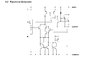
In consulting the LA5668 data sheet below . . .

We see the pin #1 solid state switched direct thru DC output is being rated a 1 amp, and the most current consuming device on the unit, is being the LA4127 Audio Power Output and it is consumimg nowhere near that resultant wattage.
And do denote that they aren't even incorporating any additional heatsinking being clamped onto its exposed top dissipation plate.

The pin # 8 +5VDC regulated digital supply is rated at 100 milliamperes.

Also the regulators pin # 6 regulated AVDD 5+ supply is also being rated at 100 milliamperes.

TESTING THE PROBLEMATIC UNIT OF THOSE TWO 5VDC SUPPLY OUTPUTS . . . . .

Initially, you could take a short cut by starting up at the output at pin 6 and measure ACROSS the sole 22 ohm resistor at its side.
If you the read in the order of 160 millivolts across it, then there is no overloading / excess current being pulled by these three branched loads, upon the regulators pin 6 . . . AVDD 5+ supply line.
Next, you move metering ,to then being from + meter to pin 6 and meter neg lead being star ground for that test ( with clip leads or use an assistant)

Now observe that the nearby 22 ohm resistor uses a quite circuitous foil path to finally reach down to connecting into another 22 ohm resistor that has its other end then connecting into pin # 4 of the LC7881C I.C.
Well . . . . . if you were to keep an eye on metering and then short that pin 4 to ground, you would then have simulated an ~ 100 ma loading upon that pin
# 6 power supply section.
That ground connection is being as close as the nearby pin # 5 which tiess into a massive foil groundplane.
CAVEAT:
That action is placing the power limit on those two resistors, so do it for no longer than is needed to see your meter reading change. Log it down.

Now since we have a known good LA5668 in use . . . .
does that voltage even change at a 100 ma drain upon its circuit or does it pull down to a slightly lower voltage OR does it drop on down to that past familiar 1.25 volt level ?

A further step in the same nature is to keep monitoring #6 voltage and then move down to that sole first 22 ohm resistor that feeds down into all of the other circuits and ground its other side.***
That would then be asking 200 ma from that regulator , then that would give the voltage figures for a severely overloaded circuit .
Of course . . . . the same BE QUICK ! *** applies at this 200 + % degree of overloading.

IF both of you were to do this, you could then compare readings and at least have a . . . BENCHMARK OF REFERENCING
for this regulator, when being in its fully operable state.
Valuable info, both for yourselves for any future encounters AND for others that stumble upon this condition, with their units.

BTW . . . .vbplayer . . . . Should you have had to use it on your 7805 sub situation . . .they make a turn on / turn off version of a +5V linear regulator as a 4 pinned Panasonic AN7805R
https://datasheetspdf.com/pdf/515639/Panasonic/AN78M05R/1


On the ACID flux contamination,it is just according to the amount used.
A scrub down with a thick paste of baking powder and water solution using a stiff brush and then thorough water rinse offs should neutralize any acidic surface contamination.
If acid is intermixed within a solder joint, you need to wick off the contaminated joint and rework with the joint then being all rosin core based solder..
A neglected contamination can result in the solder joints, time related, turning a dark gray or black and the board foil speaks for itself with recurring humidity moisture .
E.G. . . . . .

upload_2021-4-2_12-50-7.png

DATA SHEET . . . . .

upload_2021-4-2_12-51-29.png


73's de Edd . . . . . .

upload_2021-4-2_12-52-50.png

.


.
 
Top