Maker Pro
Maker Pro

Hot Wire Cutter Power Supply

sferrari

Aug 31, 2013
10
Joined
Aug 31, 2013
Messages
10
A few months ago I bought a bunch of parts to build a power supply for a hot wire foam cutter, but I shelved the project when it got complicated and I got busy. I have some time to work on it today and I'm having the same problems which stalled this thing in my previous attempt; I'm just not smart enough.

There are a lot of smart/knowledgeable people on this forum so I'm hoping a few of them can help me figure this thing out.

I bought a diehard battery charger and a fan dimmer(lutron FS-5F) hoping I would be able to connect the dimmer upstream of the transformer in the charger and have a functioning power supply. No dice. The info sheet that came with the dimmer states "CAUTION: To avoid overheating and possible damage to other equipment, do not use to control receptacles, fluorescent lighting fixtures, or transformer-supplied appliances." I don't know if the battery charger is a "transformer-supplied appliance" but it certainly has a transformer inside. I've been reading about forward and reverse phase dimmers and a variety of other control methods and my brain is fried. I don't know what to do.

Will it work? What do I have to do/buy to make it work?


The charger is pretty basic


Input: 120VAC 1.3A
Output: 12VDC 2/6A


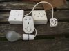
...and the back of the dimmer. I haven't the foggiest clue WTF is going on back here. Here is the link to the installation guide for the dimmer. It may/may not be relevant.
 

duke37

Jan 9, 2011
5,364
Joined
Jan 9, 2011
Messages
5,364
The battery charger has a nice looking transformer inside.

The dimmer looks to be a triac controlled supply but I cannot see the triac.
Using a triac into a transformer can give problems if the waveform is not symmetrical, this can give saturation of the core and big pop. This can be alleviated by putting a filament lamp in series between the two but is a messy and perhaps dangerous method.

Better solutions are to use a variable autotransformer (Variac, Regavolt) or use the output of the charger is is and then run regulators from this.
 

KrisBlueNZ

Sadly passed away in 2015
Nov 28, 2011
8,393
Joined
Nov 28, 2011
Messages
8,393
So you wanted to use a battery charger as a power supply to power your hot wire foam cutter?

I agree with Duke that using a lamp dimmer with a transformer-based circuit may not work properly and could cause damage.

The important factor is the characteristics of your hot wire foam cutter. I expect it uses a fairly low voltage and a fairly high current. In that case, I would power it from a 50/60 Hz transformer with a low-voltage, high-current secondary, and use a variac to vary the primary voltage.

There could be other options. For example, a PC power supply is a cheap and convenient source of low voltage at high current, and they can be modified for custom applications.

Do you have any specifications or data on the hot wire foam cutter? If so, please post it here.
 

sferrari

Aug 31, 2013
10
Joined
Aug 31, 2013
Messages
10
The battery charger has a nice looking transformer inside.

The dimmer looks to be a triac controlled supply but I cannot see the triac.
Using a triac into a transformer can give problems if the waveform is not symmetrical, this can give saturation of the core and big pop. This can be alleviated by putting a filament lamp in series between the two but is a messy and perhaps dangerous method.

Better solutions are to use a variable autotransformer (Variac, Regavolt) or use the output of the charger is is and then run regulators from this.

Yeah, the triac is there but you can't see it in the picture. I'm a broke-ass so I'm kinda interested in this lightbulb method. Why would it be dangerous to put a lightbulb in series? it would go between the dimmer and the transformer, right? The asymetrical wave creates DC where only AC should be present? Voltage spike? I don't know what core saturation is.

I've seen people mention use of a variac for the hot wire cutter power supply. They aren't cheap and I was trying to avoid having to start from scratch and spend a bunch of money. Also, they are dangerous-ish because they don't provide electrical isolation.
 

Externet

Aug 24, 2009
891
Joined
Aug 24, 2009
Messages
891
I would use a pistol soldering gun instead of a battery charger. Connect the wire to heat up instead of the tip.
If less heat wanted, then use a plain dimmer with it.
 

sferrari

Aug 31, 2013
10
Joined
Aug 31, 2013
Messages
10
So you wanted to use a battery charger as a power supply to power your hot wire foam cutter?

I agree with Duke that using a lamp dimmer with a transformer-based circuit may not work properly and could cause damage.

The important factor is the characteristics of your hot wire foam cutter. I expect it uses a fairly low voltage and a fairly high current. In that case, I would power it from a 50/60 Hz transformer with a low-voltage, high-current secondary, and use a variac to vary the primary voltage.

There could be other options. For example, a PC power supply is a cheap and convenient source of low voltage at high current, and they can be modified for custom applications.

Do you have any specifications or data on the hot wire foam cutter? If so, please post it here.

My hot wire cutter is any length of nichrome wire. I'd like to be able to use different lengths of wire for different jobs. I left my multimeter at work so I can't test the resistance but I think it's around 1.5-2ohms/foot. I think it's 24-26 gauge.

More resistance=higher current? Higher current=hotter wire? A longer wire would draw more current? The 2A/6A switch on the front could compensate for use of a longer resistance wire? The ammeter on the front would tell me if I'm overloading the transformer?

Is there any safe/reliable way to refrain from using resistance to control heat? I like the dimmers because they just cut off a portion of the wave. Would a reverse phase dimmer be safer/more reliable or would it be just as susceptible to an asymmetrical wave/DC? Would the asymmetrical wave damage the transformer or would it just damage the dimmer?

The regulators that were previously mentioned would regulate voltage and increase current? I'm not really familiar with regulators.

Oh, and I'm not sure if you guys noticed but the chargers output is DC. How does that work? I suspect one of the other two components in the circuit are a big diode? Could/should I remove one of those components and have 12VAC output? What are the other two components?


duke37

Jan 9, 2011
5,364
Joined
Jan 9, 2011
Messages
5,364
I helped my neighbour make one a short time ago and I have arranged to photograph it tomorrow.

The danger is that any works with mains voltages has to be done properly. If you use a Variac, then you should also use the battery charger or another transformer to provide isolation.

The core of a transformer is energised one way, then when the voltage reverses (AC) it is energised the opposite way. If the positive and negative voltage excursions are not similar, then there is a DC component which will push the core to one side and may take the core past its limit (saturation), then there is only the transformer wire resistance to limit the current.

On the one I made, the dimmer would work at low level where the current would be low and would also work at high level where the waveform was almost complete. It created a buzz at intermediate levels which did not sound good. A bulb in series limits the peak current so saturation is less of a problem.

You will need to determine the voltage and current of the heater wire that you use. Different wire need different voltages and current but the power did not differ much.
The cutter was made to cut foam polystyrene..
 

duke37

Jan 9, 2011
5,364
Joined
Jan 9, 2011
Messages
5,364
The cold wire resistance will be less than the hot resistance so you will need to measure both voltage and current. A longer wire will need more voltage but not more current.

AC or DC will do the same job, I would not modify the charger.

There is likely to be a bridge rectifier in the charger, this will have four terminals, marked ~~+- . There may be an over current trip which may need a reset knob or may reset itself when cooled down.
 

sferrari

Aug 31, 2013
10
Joined
Aug 31, 2013
Messages
10
The first pic is probably the overload/breaker and the second is the rectifier.
 

solo2racr

Aug 21, 2013
142
Joined
Aug 21, 2013
Messages
142
Just thought I would throw this out there.....I have used a model railroad power supply before for a hot wire foam cutter with good results. You can adjust the voltage from 0 to 18 vdc. I used ni-chrome wire for the cutter, stretched across a bow.
 

sferrari

Aug 31, 2013
10
Joined
Aug 31, 2013
Messages
10
Just thought I would throw this out there.....I have used a model railroad power supply before for a hot wire foam cutter with good results. You can adjust the voltage from 0 to 18 vdc. I used ni-chrome wire for the cutter, stretched across a bow.

I've read that the new train power supplies are equipped with something, maybe a thermal overload switch, that prevents them from performing adequately; and the older ones are hard to find/expensive. Besides, I really didn't want to spend a lot of additional money on this.

Is there a CHEAP/reliable/safe way to control the battery charger output to control wire temperature?
 

KrisBlueNZ

Sadly passed away in 2015
Nov 28, 2011
8,393
Joined
Nov 28, 2011
Messages
8,393
Your comment about a variac being dangerous because it doesn't provide electrical isolation is not relevant here; you would not power the cutter directly from the variac's output. A transformer would be needed, to step down the 0~115VAC or 0~230VAC from the variac to a lower voltage and higher current to suit the cutter.

But that's not important because you won't be buying a variac.

The PWM motor controller you linked to should be good for your application. You can power it from the battery charger. You may need a smoothing capacitor across the output of the battery charger because lead-acid battery chargers often have no smoothing after the rectifier; they charge the battery in pulses at the AC mains frequency. That's fine for charging a lead-acid battery but the PWM controller expects a reasonably continuous DC input voltage.

I would use an electrolytic capacitor of about 4700 uF rated for at least 25V (if the charger is designed for 12V batteries) or 16V (if the charger is designed for 6V batteries).

You should set the charger on its high current setting and adjust the PWM motor controller to get the desired temperature in your cutting wire.

The PWM circuit you are considering is a voltage control system. It operates by passing its input voltage through to its output through a switching device (a transistor or MOSFET), which is turned ON and OFF very quickly. In this case, 15,000 times per second (the PWM frequency is 15 kHz).

A heating wire cannot heat up and cool down 15,000 times per second, so it responds to the AVERAGE (MEAN) voltage. So if the PWM circuit is powered from, say, 12VDC and is operated with 10% duty cycle (the switching device is ON for 10% of the time, and OFF for 90% of the time), the wire will "see" 1.2VDC across it.

A PWM controller is very similar to a lamp dimmer - in fact, a lamp dimmer is a special type of PWM controller - but lamp dimmers operate at mains frequency (twice mains frequency, actually) and cut off different parts of a sine wave, whereas PWM controllers operate at a much higher frequency and use a constant DC voltage input.

Re your questions about voltage, current and resistance. They are related by a formula called Ohm's Law. It's probably the most basic and important law in electronics. Ohm's Law states:

I = V / R

where I is current, measured in amps; V is voltage in volts, and R is resistance in ohms.

Nichrome wire is resistive, as you say. Something like 2 ohms per foot, so the resistance is proportional to the length of wire that you're using. The resistance also varies somewhat with the temperature of the wire - as it gets hotter, its resistance increases.

Voltage is a quantity that you APPLY to the wire, and it is measured ACROSS the wire, i.e. BETWEEN two points (the two ends of the wire).

Current is a quantity that FLOWS IN the wire, and is measured at a single point in a circuit.

Applying voltage across a resistance (the wire) causes current to flow in the wire. The amount of current that flows can be calculated using Ohm's Law, if you know the applied voltage and the resistance. But remember that the resistance will increase somewhat with increased temperature.

When a resistive component has voltage across it, and current flowing through it, POWER is dissipated; this is the quantity that determines the amount of heat generated.

Power can be calculated as P = V I (power is voltage multiplied by current), where P is power, in watts, and V and I are voltage and current as before.

You're interested in using different wire lengths. Doubling the wire length will double its resistance. It also doubles the amount of power you need to dissipate to keep the wire at the same temperature, because the power is dissipated over twice the length.

Doubling the resistance and doubling the power means that you have to double the voltage applied. In other words, the voltage you need to apply is proportional to the length of the wire.

You may also be able to see that the amount of current required, to achieve a given wire temperature, is the same regardless of the length of the wire. This means you could actually power your wire from a special type of circuit called a current regulator, which applies whatever voltage is necessary to obtain a specific current flow. This would allow you to vary the wire length without making any adjustments. If you control the voltage, you will need to adjust it according to the length of the wire.

You can actually convert a switching supply into a current regulator with minor modifications. Small switching supply modules are available cheaply from eBay. This is perhaps the best approach, but you can start with the PWM module if you like. It would be useful to know how much current your wire needs for this application. You can measure that with a multimeter, set to the 10A range, connected in series with the cutter wire. Adjust the voltage for the desired temperature and see how much current is flowing.

Sorry if this is a bit long and technical. It's a bit of a brain dump. You might want to re-read it a few times; it should become clear eventually. I hope!
 

sferrari

Aug 31, 2013
10
Joined
Aug 31, 2013
Messages
10
Your post wasn't excessive. That was perfect: EXACTLY what I needed.

I feel confident I can move forward with this thing now. I'm gonna order parts and update this thread when I start assembly. You have a lot of other good ideas and stuff I want to discuss but I'm burnt out right now and I want to get some rest.

Thanks
 

duke37

Jan 9, 2011
5,364
Joined
Jan 9, 2011
Messages
5,364
I attach some photos of the lamp protected dimmer. The transformer is 24V and the length of the wire is 1m.

I also show a series lamp which can be used to slowly power old valve radios or devices which have a tendency to blow fuses on switch on.

If the lamp is broken, then there will be live connections exposed so be careful.

The EU have banned normal filament filament lamps so I will have difficulty when these bite the dust.
 

Attachments

  • HotWire 001.jpg
    HotWire 001.jpg
    149.7 KB · Views: 328
  • HotWire 002.jpg
    HotWire 002.jpg
    141.3 KB · Views: 314
  • HotWire 004.jpg
    HotWire 004.jpg
    158.7 KB · Views: 224

Fish4Fun

So long, and Thanks for all the Fish!
Aug 27, 2013
481
Joined
Aug 27, 2013
Messages
481
sferrari,

You might give some serious consideration to forgoing all of these excellent suggestions and consider a simple approach: Adjust your length of wire to the power supply you already have. @ 2 ohms per foot 5 feet would be 10 ohms or roughly 1.44A (A typical 12V battery charger's output is 14.4V). If you spend a bit of time configuring your "bow", you can adjust the distance between the "stretched part" while leaving the "un-stretched part" of the wire connected to maintain the proper resistance. In this case you only have to worry about keeping the "un-stretched" wire in a safe position. If you need the wire hotter, simply move the connecting wires a bit closer together. I realize this is a bit crude, but it will work just fine if you pay careful attention to the design/construction of your "bow".

Fish
 

sferrari

Aug 31, 2013
10
Joined
Aug 31, 2013
Messages
10
I got my PWM in the mail and I got that capacitor from radioshack.


The transformer wasn't as straight-forward as I'm accustomed to and it didn't have any markings indicating how it works. I wanted to understand what was going on inside so I tinkered with it and broke it. Now it's garbage and I'm gonna have to buy a new one. This sucks.


The rectifier is confusing me too. Shouldn't there be two leads for the AC and two for the DC? I only see three; the two black wires and the plate it's riveted to.


KrisBlueNZ

Sadly passed away in 2015
Nov 28, 2011
8,393
Joined
Nov 28, 2011
Messages
8,393
The black, purple and yellow wires look like they connect to the primary of the transformer, which is wound with thinner wire than the secondary. I can't see the connections to the secondary.

Assuming that the white thing mounted against the plate is a rectifier of some kind, there are two possibilities: either (a) it's a single diode used as a half-wave rectifier, or (b) it's a double diode with the common terminal connected to the metal part of the package that makes contact with the heatsink, used as a full-wave rectifier with a centre-tapped secondary. I suspect (b) because it would give a balanced output current.

The way to tell is by the number of connections to the secondary. These are on the side of the transformer that's not visible in the photos. If there are two wires, it's (a), a half-wave rectifier. If there are three wires, it's (b), a full-wave rectifier with a centre-tapped secondary. It looks like there are two black wires and a blue wire coming from the secondary.

If you have to replace the charger, why not buy the proper thing - a low-voltage, high-current mains-powered power supply? We still don't know how much current you need; perhaps you could borrow a suitable power supply to test with, to see how much current it takes to get the wire up to a suitable temperature?

I'm not sure how you want to proceed.
 

duke37

Jan 9, 2011
5,364
Joined
Jan 9, 2011
Messages
5,364
The idea of using a battery charger is a good one, it gives a lower voltage, measures current and is isolated from the mains. In other words, it is reasonably safe to handle.

So why did you muck about with it?
If you do manage to get it working again, will it be safe?
 

sferrari

Aug 31, 2013
10
Joined
Aug 31, 2013
Messages
10
The black, purple and yellow wires look like they connect to the primary of the transformer, which is wound with thinner wire than the secondary. I can't see the connections to the secondary.

Assuming that the white thing mounted against the plate is a rectifier of some kind, there are two possibilities: either (a) it's a single diode used as a half-wave rectifier, or (b) it's a double diode with the common terminal connected to the metal part of the package that makes contact with the heatsink, used as a full-wave rectifier with a centre-tapped secondary. I suspect (b) because it would give a balanced output current.

The way to tell is by the number of connections to the secondary. These are on the side of the transformer that's not visible in the photos. If there are two wires, it's (a), a half-wave rectifier. If there are three wires, it's (b), a full-wave rectifier with a centre-tapped secondary. It looks like there are two black wires and a blue wire coming from the secondary.

If you have to replace the charger, why not buy the proper thing - a low-voltage, high-current mains-powered power supply? We still don't know how much current you need; perhaps you could borrow a suitable power supply to test with, to see how much current it takes to get the wire up to a suitable temperature?

I'm not sure how you want to proceed.

I patched up the transformer and plugged it in today. It seems to work ok. I'm might as well assemble this thing and give it a go. I hooked up my multimeter and got some numbers. On the 2A setting it puts out 11.5V and 14.2V on the 6A setting. The resistance wire is 1.8ohms/ft.

2A setting w/ 1ft wire @ 100% duty cycle --- 11.5V/1.8 = 6.39A
6A setting w/ 1ft wire @ 100% duty cycle --- 14.2v/1.8 = 7.89A

The ammeter on the front of the charger suggests that 2A and 6A is the max current so using those values, I wouldn't be able to use a 1 foot wire on either setting. It would draw too much current.

2A setting w/ 4ft wire @100% duty cycle --- 11.5V/(1.8*4) = 1.59A
6A setting w/ 14in wire @100% duty cycle --- 14.2V/(.15*16) = 5.92A

I figure I could build a table with a 14 inch wire and a bow with a 4 foot wire.

The secondary has three wires. I suspect it's a double diode rectifier.

I'm assuming this thing is a fuse?


12A is probably too much if the max output of the PWM is 8A?


Where should I put circuit breakers/fuses?


How should I put this capacitor in? It's kinda big. I feel like just soldering it to some wires would be inadequate. Should I zip tie it to something? Is there another method for securing it that would be better?

The idea of using a battery charger is a good one, it gives a lower voltage, measures current and is isolated from the mains. In other words, it is reasonably safe to handle.

So why did you muck about with it?
If you do manage to get it working again, will it be safe?

I screwed with it because I'm an idiot.

I'd be lying if i said it was safe. I'm gonna do it anyways.
 
Top