Maker Pro
Maker Pro

Hp laptop adapter fail

73's de Edd

Aug 21, 2015
3,622
Joined
Aug 21, 2015
Messages
3,622
Sir pharaon . . . . .


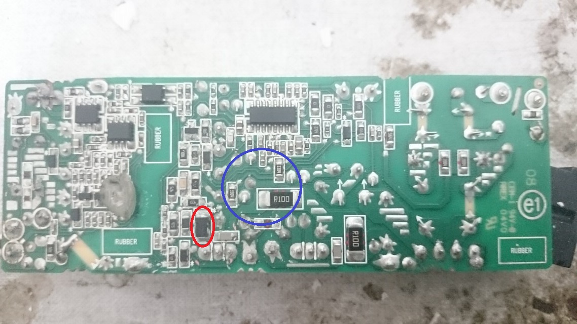
Ahhhhhhh . . . yes their design must have the two N-FETS arranged in series and the higher voltage rated unit is connected closer to the 330 VDC source, with the other one being below it to ground.

You certainly did a good job in getting the white silicone rubber from the foil side of the board.
In post 17 you have 3 board pictures , the top one looks good with all parts on it
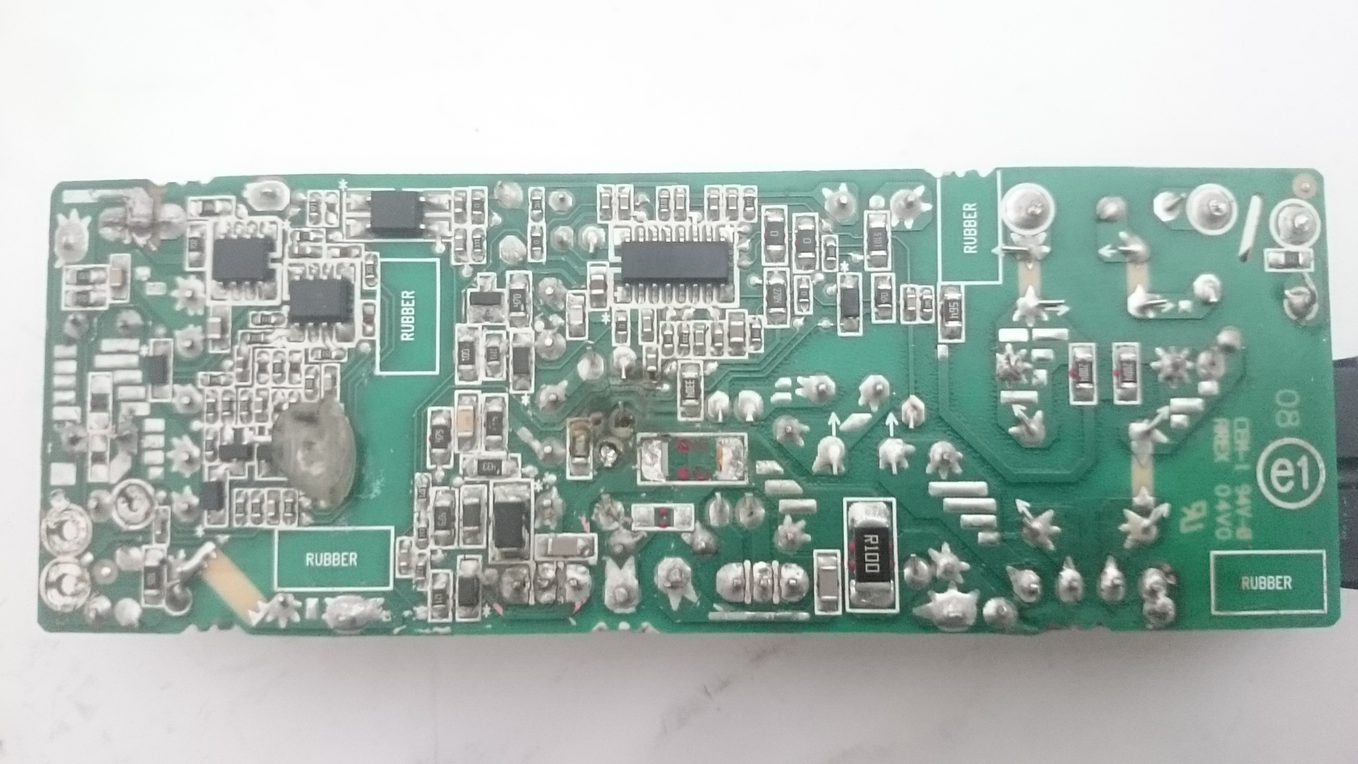
The botom picture looks good with one R100 pulled
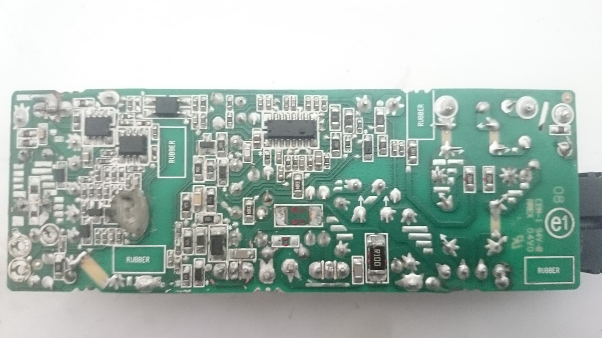
BUT the middle one looks dismal in its center area, I hope that is not the PRESENT state of the board.

There is no chance that you are just plugging this board in to test it . . .is there ?

It should always be tested with a 60 watt incandescant lamp wired in place of the fuse OR be wired in series with one of the ac power wires coming into the board.

Just want to confirm that .

73’s De Edd
 

pharaon

Oct 28, 2014
444
Joined
Oct 28, 2014
Messages
444
Well in previous post it below because i was measuring the dc volt on it
So I'll replace the resistance
But what test exactly you want me to do
 

pharaon

Oct 28, 2014
444
Joined
Oct 28, 2014
Messages
444
There is no chance that you are just plugging this board in to test it . . .is there ?

It should always be tested with a 60 watt incandescant lamp wired in place of the fuse OR be wired in series with one of the ac power wires coming into the board

What test you want me to do since there's no output DC volt
Do you want me to test certain parts
 

KilgoreCemetery

Apr 12, 2017
258
Joined
Apr 12, 2017
Messages
258
I'm super new at this, so take this with a grain of salt, but my understanding is that the transformer is supposed to convert AC to DC with the help of a rectifier. What voltage is going into the transformer and what voltage is coming out?
 
Last edited:

KilgoreCemetery

Apr 12, 2017
258
Joined
Apr 12, 2017
Messages
258
Also, I just re-read post 17 and realized that you said the 330V you measured was DC? Again, I'm a complete noob with this stuff, but what is the point of increasing the DC voltage to that amount when the goal is to get a 19VDC output?
 

davenn

Moderator
Sep 5, 2009
14,260
Joined
Sep 5, 2009
Messages
14,260
I'm super new at this, so take this with a grain of salt, but my understanding is that the transformer is supposed to convert AC to DC with the help of a rectifier. What voltage is going into the transformer and what voltage is coming out?

Also, I just re-read post 17 and realized that you said the 330V you measured was DC? Again, I'm a complete noob with this stuff, but what is the point of increasing the DC voltage to that amount when the goal is to get a 19VDC output?

this is because you don't understand how SMPS .. switch mode power supplies work ;)

The incoming 220-240VAC mains voltage is directly rectified producing around 300 or so VDC ( that will be lower for countries that use 110-120VAC). It is then switched with an oscillator at 40kHz or more ( some of the more modern ones can be up to several 100 kHz). That resulting voltage is across a primary of a transformer ( a transformer that is only a fraction of the size of a transformer in a linear PSU) The lower voltage high from the secondary of the transformer is then rectified, smoothed and sent to the output as the final DC voltage.
There is also a feedback voltage that comes from the output stage and back to the high voltage input stage to do voltage regulation

here I have annotated a SMPS schematic showing you those different sections


upload_2017-4-23_8-6-57.png


Dave
 

pharaon

Oct 28, 2014
444
Joined
Oct 28, 2014
Messages
444
Nice information dave
But still why no output in my adapter i don't understand since all parts is working
 

KilgoreCemetery

Apr 12, 2017
258
Joined
Apr 12, 2017
Messages
258
Thanks for the info Dave, and thanks for the diagram. I tend to be a very visual person. I'll have to read up on that some more to understand it a bit better though.
 

davenn

Moderator
Sep 5, 2009
14,260
Joined
Sep 5, 2009
Messages
14,260
But still why no output in my adapter i don't understand since all parts is working

well obviously not all parts are working aye ? ;)
did you replace that 10 Ohm SMD resistor ?
there's so many other transistors, diodes and IC's on the board, any one or more could have failed when the output went short circuit

To be totally honest, the chances of repair is highly unlikely for a SMPS as complex as this one
if it was mine, I would have checked the usual parts as has already been gone through by Edd and us others. If none of them fixed the fault
I would have binned it and got a replacement.
Had the SMPS been a more simple design like the one in my schematic above, there would have been a higher chance of fixing it


Dave
 

73's de Edd

Aug 21, 2015
3,622
Joined
Aug 21, 2015
Messages
3,622
Sir pharaon . . . .et al . . .

UNTIMELY UPDATE:

With our Right Honourable, Revered and Esteemed DAVENN . . . is going to say this, having already said this , or wanting to say this . . . or LIKING my having said this . . . . .

I do now believe that the PA-1900-05 schematic which I have located out of Hong Kong will be close enough to your PA-1900-32HN (as in HK) to work with .

You never did look me right in the eye and tell if you had plugged this directly into AC power, without the utilization of a series INCANDESCENT lamp to provide protection in case of an overload or a direct short.

With my now being able to see that resistor as functioning as the series element in the gate drive from the power control IC to the gate of one of the SK35XX Power FETs I don’t see that 10 ohm resistor blowing without a shorted FET and FULL AC voltage being applied to the unit.

Schema to follow after its mark up and prep . . .’cause some of it will otherwise be real-real screwy to the uninitiated .


73’s de Edd
 
Last edited:

pharaon

Oct 28, 2014
444
Joined
Oct 28, 2014
Messages
444
You never did look me right in the eye and tell if you had plugged this directly into AC power, without the utilization of a series INCANDESCENT lamp to provide protection in case of an overload or a direct short

yes i plugged it directly to the AC power and tried to measure VDC over the board when i get it shorted as in this image....i measure VDC over two sides on red circuit part and get shorted in the blue area like the image

DSC_0372.jpg


DSC_0380.jpg


and this after i clean it
DSC_0381.jpg


so first i need to replace the damage parts before i can test again with lamp

the damaged parts is

R100 resistor
the second R100 resistor gave me 1 Ohm on avometer so i assume it's bad too

the k3569 in post 16 got shorted

and i don't know yet what else could be damaged

the k3569 can't find it right now in my city hope if there's another replacement part can do it's work
 

davenn

Moderator
Sep 5, 2009
14,260
Joined
Sep 5, 2009
Messages
14,260
so first i need to replace the damage parts before i can test again with lamp

yes

the second R100 resistor gave me 1 Ohm on avometer so i assume it's bad too

100 = 10 Ohms
R100 will be either 1 Ohm or 0.1 Ohm I personally wouild have gone for 0.1 Ohm as the R position usually signifies the decimal point position
eg. 1R5 = 1.5 Ohms
 

pharaon

Oct 28, 2014
444
Joined
Oct 28, 2014
Messages
444
100 = 10 Ohms
R100 will be either 1 Ohm or 0.1 Ohm I personally wouild have gone for 0.1 Ohm as the R position usually signifies the decimal point position
eg. 1R5 = 1.5 Ohms

so that mean the R100 is working fine?
and i shuld replace the blowing R100 with 1 Ohm resistor not 10 Ohm?
 

davenn

Moderator
Sep 5, 2009
14,260
Joined
Sep 5, 2009
Messages
14,260
and i shuld replace the blowing R100 with 1 Ohm resistor not 10 Ohm?

I would go for a 1 Ohm

but until you discover what else is faulty, you will only blow it again
but as I said up the page, that is going to be difficult with all the unknown IC's etc on the board
 

pharaon

Oct 28, 2014
444
Joined
Oct 28, 2014
Messages
444
but as I said up the page, that is going to be difficult with all the unknown IC's etc on the board
tell me what IC's you want to know and I'll get you it's number right away
there's a lot of images just make circle around the part you want it's details and i'll get it
 

pharaon

Oct 28, 2014
444
Joined
Oct 28, 2014
Messages
444
on diode scale in my multimeter i tested that piece with circles around it
there's short(beeb) between the blue circle leds
the red circle leds give reading like 1.023 and 1.300 on diode scale

the number of that piece is lx9 375 x

i guess that mean it's not working right

 
Top