Maker Pro
Maker Pro

Identify SMD IR photo diode

loopguru

Nov 18, 2012
6
Joined
Nov 18, 2012
Messages
6
I'm not very professional when it comes to electronics. Unfortunately I destroyed a SMP IR photo diode when I unsoldered it. It was together with a IR LED part of a light barrier for an electronic cat flap. My plan was to relocate the LED and the diode into a separate housing.

So I'm looking now for a replacement for both of them. The LED is still intact so I guess it will not be too hard to find something similar. I even could use the original LED but I don't know the IR wavelength. For the diode one can only guess. The cat flap runs with four 1,5 Volt AA batteries.

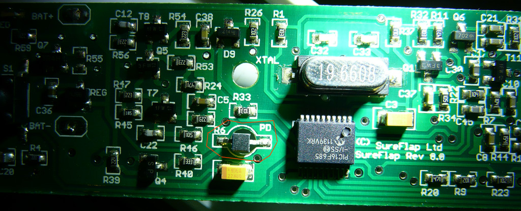
Here a picture from the board. I marked the destroyed photo diode in red.
sureflapdarox.jpg


Any idea what I could try as a (non SMD) replacement?

Thanks,
Thomas
 

(*steve*)

¡sǝpodᴉʇuɐ ǝɥʇ ɹɐǝɥd
Moderator
Jan 21, 2010
25,510
Joined
Jan 21, 2010
Messages
25,510
If one is an IR LED and the other is an IR photodiode, then you should be able to get pretty much any pair of devices that will work together.

They shouldn't be critical, but connecting them around the right way will be!
 

loopguru

Nov 18, 2012
6
Joined
Nov 18, 2012
Messages
6
If one is an IR LED and the other is an IR photodiode, then you should be able to get pretty much any pair of devices that will work together.

Thanks a lot, Steve!

After your info I looked up a KEMIC T153 pair.

What irritates me is that the T153 contains a photo transistor and not a photo diode. As I researched in the Internet a photo transistor is more common for light barriers.
I hope it works because on the board there is "PD" printed which I translated with photo diode.

They shouldn't be critical, but connecting them around the right way will be!

On my board the IR LED and the IR PD had one side marked in blue color. For the LED I assume the marked side is the cathode.

For the photo diode I'm unsure what the blue side means. Does this translate to the emitter or collector of the photo transistor?

Regards,
Thomas
 

(*steve*)

¡sǝpodᴉʇuɐ ǝɥʇ ɹɐǝɥd
Moderator
Jan 21, 2010
25,510
Joined
Jan 21, 2010
Messages
25,510
If you believe it's a photodiode, then you're best replacing it with another photodiode.

However, it's possible that PD means photo-detector...

Presumably the phototransistor you have is NPN, and as such, the collector should be more positive than the emitter.

You should try to trace the circuit and determine which way around you should put it.
 

loopguru

Nov 18, 2012
6
Joined
Nov 18, 2012
Messages
6
Presumably the phototransistor you have is NPN, and as such, the collector should be more positive than the emitter.

You should try to trace the circuit and determine which way around you should put it.

I will try so. After some research in the web I saw that SMD photo transistors have an emitter mark. Could not find one with collector mark. So I guess the blue mark on my broken PD element was the emitter.

Thanks,
Thomas
 

loopguru

Nov 18, 2012
6
Joined
Nov 18, 2012
Messages
6
If you believe it's a photodiode, then you're best replacing it with another photodiode.

However, it's possible that PD means photo-detector...

Presumably the phototransistor you have is NPN, and as such, the collector should be more positive than the emitter.

You should try to trace the circuit and determine which way around you should put it.
Ok, I traced it now but the result is confusing. If you look on the photo in my first post you can see that the right side of the 'PD' is connected to 'BAT -'. I verified this.
But the marked side (with blue color) of the PD is the left side. If you look hard you can even see this on the photo.

  • If PD is a diode than normally the cathode is marked blue. But in such a case the cathode would be connected to the positive side - makes no sense.
  • If PD is a NPN transistor than normally the marked side is the emitter. Doesn't make sense either as in this case the collector is connected to BAT -
Regards,
Thomas

P.S.: I did some more research and found a SMD phototransistor with a collector mark (PT15-21C/TR8). So there seems to be no standard what to mark. Confusion resolved.
 
Last edited:

(*steve*)

¡sǝpodᴉʇuɐ ǝɥʇ ɹɐǝɥd
Moderator
Jan 21, 2010
25,510
Joined
Jan 21, 2010
Messages
25,510
If PD is a diode than normally the cathode is marked blue. But in such a case the cathode would be connected to the positive side - makes no sense.

No, that makes sense. A photodiode is often connected reverse biased in a circuit.

Google for "photodiode detector schematic" and look at the images it finds.
 

loopguru

Nov 18, 2012
6
Joined
Nov 18, 2012
Messages
6
Google for "photodiode detector schematic" and look at the images it finds.
Thanks, that was really a surprise. I thought a photo diode is used like a diode - but it seems photo diodes are normally used in reverse order (as input for a transimpedance amplifier).

This makes it now interesting: I assume if I replace a photo diode with a photo transistor nothing will happen. Let's see - my parts should arrive soon. Sureflap - the producer of the cat flap - is not coming back to me so I can only guess.

Thanks,
Thomas
 

loopguru

Nov 18, 2012
6
Joined
Nov 18, 2012
Messages
6
Thanks!

Hi Steve,

thanks a lot! Based on what you wrote I was today able to get a replacement working. The

First I tried a phototransistor with emitter to minus.
The cat flap was working, but weird - somehow with inverse than expected behavior.

Then I ordered a photo diode (BPV23NF) and used it reverse biased. Works perfectly!

Best regards,
Thomas
 

(*steve*)

¡sǝpodᴉʇuɐ ǝɥʇ ɹɐǝɥd
Moderator
Jan 21, 2010
25,510
Joined
Jan 21, 2010
Messages
25,510
Great!

The phototransistor may have worked if you had used the base-collector junction as it is normally reverse biased (and the BE junction will break down under a relatively small reverse voltage).

However, the photodiode is the *right* device, and I'm glad you got it all working again.
 
Top