Maker Pro
Maker Pro

Identifying Cracked Diode on Mecedes Key Fob

Status
Not open for further replies.

elginowens

Feb 28, 2014
11
Joined
Feb 28, 2014
Messages
11
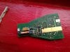
My friends Mercedes Benz C230 key fob quit working so I took it apart and found a diode on the circuit board that is cracked. I can't find any schematics for the circuit so I'm hoping someone here can help to identify the diode so that I can purchae a replacement. I've attached some pics of the circuit board the component in question is the glass diode with orange body I believe it has a black ring towards the middle it's hard to tell since it is cracked. On one end there is definitely a large yellow band.

I believe the part of the circuit that this diode is in has to do with the immobilizer system built into the smartkey fob. The infrared locking system part of the remote seems to be working but I believe that when the remote is inserted into the dash keyhole to start the car induces voltage into the coil on the key fob circuit which signals the remote to send infrared pulses to the car and dissables the immobilizer.

Please let me know how I can go about identifying this diode or if you think it would be safe to put in it's place another Zener diode. The diode that I have available to try is IN4742A 12V 21ma max power dissipqttion 1.0w
 

Attachments

  • IMAG1038.jpg
    IMAG1038.jpg
    150.6 KB · Views: 2,277
  • IMAG1034.jpg
    IMAG1034.jpg
    151.7 KB · Views: 1,443
  • IMAG1031.jpg
    IMAG1031.jpg
    150.4 KB · Views: 1,159

(*steve*)

¡sǝpodᴉʇuɐ ǝɥʇ ɹɐǝɥd
Moderator
Jan 21, 2010
25,510
Joined
Jan 21, 2010
Messages
25,510
I would measure the voltage across this diode.

Knowing which end is positive and what the magnitude of the open circuit voltage is would suggest if it's a regular diode or a zener diode.
 

Jagtech

Feb 22, 2014
43
Joined
Feb 22, 2014
Messages
43
It appears to be just a standard surface mount silicon diode. See DigiKey or similar for part # LL4148. If it is a zener, it would have a number on it, such as your 1n4742A.
 

elginowens

Feb 28, 2014
11
Joined
Feb 28, 2014
Messages
11
Thanks for the suggestion Steve! I rigged up the two 3.7v li-ion button cells with some leads and measured voltage across the diode with my fluke meter. It read 0.003 V DC That doesn't seem right to me. I think that it will be very hard or impossible for me to measure the correct voltage across it because the car must induce voltage into the coil on the board to power this part of the circuit. The Mercedes Benz system is different than any other ignition system I've ever seen.
 
Last edited:

elginowens

Feb 28, 2014
11
Joined
Feb 28, 2014
Messages
11
Thanks Jagtech does that mean I souldn't use the zener diode that I've got on hand? The ones I have are through hole instead of SMT but I'm just looking for a quick fix to get my friends car to start again. I was thinking about just soldering in one of my zener diodes parallel to the broken one that's in there, would that be a bad idea? If that's a bad idea then I can look into the LL4148 but I need to have it fixed like yesterday so I may have to check my local electronics supplier (sigh) Radio Shack to see if they have something comparable to the LL4148. I guess if I had to I could drive the extra hour to Fry's Electronics and get the right part.
 
Last edited:

KJ6EAD

Aug 13, 2011
1,114
Joined
Aug 13, 2011
Messages
1,114
Radio Shack will have a 1N4148 which is the leaded version of the LL4148. You can make one fit.
 

jpanhalt

Nov 12, 2013
426
Joined
Nov 12, 2013
Messages
426
The tantalum capacitor (?) (D105) and diode look like they are wired parallel.

The capacitor code indicates 20V/1uF. So I suspect the working voltage is less than 20V. Since the bar on the end of tantalums is the positive end, the diode seems to be reverse biased...implying it may be a zener.

John
 

elginowens

Feb 28, 2014
11
Joined
Feb 28, 2014
Messages
11
I think John may be on to something here... I first tried to identify the diode by the color band but have since found out that the color bands on diodes are not standardized like they are on resistors. While researching the color bands I came across this chart that's used to help identify diodes with the SOD-80 package…
http://www.marsport.org.uk/smd/sod80.htm
According to that chart since it has one yellow color band it would be one of these three; BZV55,BZV80,BZV81 series zeners. When I did a quick google search for BZV55 I found photos of diodes that look IDENTICAL to the one that I’m trying to replace, however I do understand how looks can be deceiving.
I know that datasheets often use a generic photo but here’s one where the photo looks exactly like the one I’m after. It also happens to be the 20V version like John suggested I would need, but there are several voltages to choose from and they all appear to use the same photo for the datasheet.
http://www.datasheetlib.com/datasheet/1064292/bzv55c20_multicomp.html
I’m wondering how much damage could I really cause to this circuit by installing the wrong variety of diode… I mean as long as it’s installed in the correct direction would it just not work or could it really cause devastating damage? I did a little research to try and learn about he different types of diodes and their respective application, unfortunately I didn’t really learn much. I still don’t understand why it matters if it’s a zener diode, switching diode or what.
 

jpanhalt

Nov 12, 2013
426
Joined
Nov 12, 2013
Messages
426
Let me clarify something. The 20V rating was for a tantalum capacitor. What that means is that the "zener" could not be more.

It is common practice with capacitors to use one with a voltage rating that is more than the circuit voltage, and that can be particularly true for tantalums. If exposed to overvoltage or too much ripple, tantalums can explode. Thus, it is not unusual to find tantalum voltage ratings that are at least twice the circuit voltage.

John
 

elginowens

Feb 28, 2014
11
Joined
Feb 28, 2014
Messages
11
Ok that makes sense. I think I'm going to try the 12v zener diode and see if it works. What about just soldering in the new diode on top of the old one, is that a bad idea? It just seems like it would be easier to leave the old broken one on there since I'm using a through hole replacement it would give me more are to make the connection.
 

jpanhalt

Nov 12, 2013
426
Joined
Nov 12, 2013
Messages
426
According to your post #4, the zener may have died shorted. Soldering a new diode across a short will do nothing. I suggest removing it. After you remove it, you may want to repeat the voltage test you did.

What was the key fob's battery voltage?

John
 

elginowens

Feb 28, 2014
11
Joined
Feb 28, 2014
Messages
11
The battery voltage was good, can't remember what it measured at but I did test it. The batteries are brand new. I checked continuity across the diode, inverted the probes and found nothing both ways. I'll go ahead and remove the old one just make sure it isn't an issue.

I have read that this particular part of the circuit does not require the batteries because it is powered by induction. There is a coil right next to this diode that gets voltage induced into it from the ignition. This induced voltage then powers the smartkey fob and triggers it to send infrared signals back to the car which is how the car authenticates the smartkey fob and allows you to start the car with it.

Thanks to everyone who has volunteered their time to offer me advice on this, it is ver much appreciated. I will let you all know how it goes.
 
Last edited:

jpanhalt

Nov 12, 2013
426
Joined
Nov 12, 2013
Messages
426
Finding "nothing" in a continuity test is ambiguous. It may mean the resistance was open circuit, or it may mean the resistance was zero. If effectively zero, then it is shorted.

The markings on the big mustard-colored capacitor indicate its maximum voltage is 10V. Are there any components on the other side of the board, like some sort of IC or microcontroller?

Knowing the original battery voltage would be a big help. That zener diode is probably being used as a voltage regulator or to set a fixed voltage for something in the circuit. That fixed voltage is usually less than the battery voltage.

If the zener voltage is too low, you will not damage the device. If it is too high, you might. With that 10V capacitor there, I would not put a 12V zener in the circuit, unless I was absolutely sure. Tantalum capacitors do not tolerate overvoltage very well.

John

Edit: I just re-read the part about the transponder. My Honda key was the same. It did not have a battery. Did this key fob have a battery?
 
Last edited:

elginowens

Feb 28, 2014
11
Joined
Feb 28, 2014
Messages
11
Sorry I answred your questions so poorly. First off I measured resistance there was at first something like 280k but after I probed it a couple time with my fluke 787 process meter there was infinite resistance or open circuit regardless of the probe configuration. The battery config is 2 x 3.7v li-ion buttons cells for a total working voltage of 7.4v.

The other side of the board does have two ic's or microcontrollers the guys in the Benz forum called one of them a ROM chip. I'll get you pictures after 2pm when I'm off work. This is not your typical transponder system it is quite different. Let me see if I can find an explanation of how it works because I barely understand it myself.
 

jpanhalt

Nov 12, 2013
426
Joined
Nov 12, 2013
Messages
426
MIcrocontrollers are typically 5V or 3.3V. If this is a old Mercedes, then my bias would be 5V (The entire transponder in my 2000 Honda was a glass tube <1/8" X 1/2". So that relatively huge device on a Mercedes makes me think it must be older.)

Are there any labels on the IC's you can post?

Now, if the controllers/IC's were 3.3V, they probably wouldn't have used 2 Li-ion batteries in series. So, I am guessing 5V. Put the 12V zener aside and try to find one near or slightly below 5V.

John
 

elginowens

Feb 28, 2014
11
Joined
Feb 28, 2014
Messages
11
That's what I was thinking take the 12v zener diodes back and get the 5v version instead. I found a pick of the other side of the board. The car is a 2006. Your right that a transponder is typically a very small RFID chip. This is not a transponder system. It uses an infrared led to send a signal to the cars ignition that the authorized smartkey fob is inserted into the ignition. The battery part of this smartkey fob power the keyless entry part of the pcb. Whereas the part of the PCB responsible for authorizing the car to start via the infrared pulses is powered through induction so that even if your batteries die then the smartkey can still start the car. Again I'm still looking for the explanation from someone who knows the system better than I do. Here's the link to the image of the other side of the remote... http://forums.mercedesclub.org.uk/attachment.php?attachmentid=7572&d=1242897470
 

jpanhalt

Nov 12, 2013
426
Joined
Nov 12, 2013
Messages
426
I can't make out any labels, but use a zener that is between 5.0 to 4.75. Both 5.0 and 4.8 are standard values.

John
 

elginowens

Feb 28, 2014
11
Joined
Feb 28, 2014
Messages
11
I took some more pics of the smartkey fob.
 

Attachments

  • IMAG1042.jpg
    IMAG1042.jpg
    155.8 KB · Views: 1,242
  • IMAG1046.jpg
    IMAG1046.jpg
    160.2 KB · Views: 663
  • IMAG1067.jpg
    IMAG1067.jpg
    150.8 KB · Views: 879
  • IMAG1066.jpg
    IMAG1066.jpg
    152.3 KB · Views: 980

jpanhalt

Nov 12, 2013
426
Joined
Nov 12, 2013
Messages
426
"A" is the code for 10V tantalum (as in the one labeled A106. The chip numbers are proprietary. Go with the suggested plan.

John
 

elginowens

Feb 28, 2014
11
Joined
Feb 28, 2014
Messages
11
I got a 5.1V zener diode from radio shack p/n: IN4733A it's all soldered in and ready to go back to.my friend for testing.
 

Attachments

  • IMAG1069.jpg
    IMAG1069.jpg
    153.5 KB · Views: 659
Status
Not open for further replies.
Top