Maker Pro
Maker Pro

Installing Cabinet LEDs in my Workvan

FvnnyL3tt3r1ng

Feb 26, 2015
23
Joined
Feb 26, 2015
Messages
23
I know this much, there are two separate battery compartments with separate negative connections. The positive connections are common.
 

FvnnyL3tt3r1ng

Feb 26, 2015
23
Joined
Feb 26, 2015
Messages
23
I'm going to build this circuit on the breadboard and see how it works out with my 13.8V Bench power supply..... Does anyone have any problems with this?
 

Attachments

  • VanLights.png
    VanLights.png
    19.7 KB · Views: 93

Gryd3

Jun 25, 2014
4,098
Joined
Jun 25, 2014
Messages
4,098
I'm going to build this circuit on the breadboard and see how it works out with my 13.8V Bench power supply..... Does anyone have any problems with this?
Not at all. Give it a try, It's inexpensive, but will heat up . More so as you draw more current.
Being attached to a metal body will help dissipate more heat.
 

FvnnyL3tt3r1ng

Feb 26, 2015
23
Joined
Feb 26, 2015
Messages
23
I forgot to add the series resistor in the input before the capacitor. Would wiring some 1/4W resistors in parallel share the heat dissipation?

Figuring for about 10 ohms total R I'm thinking I would need: ~14v * 1 amp = 14W....14W / 0.25W = 56 resistors? Am I going about this wrong?
 

Gryd3

Jun 25, 2014
4,098
Joined
Jun 25, 2014
Messages
4,098
I forgot to add the series resistor in the input before the capacitor. Would wiring some 1/4W resistors in parallel share the heat dissipation?

Figuring for about 10 ohms total R I'm thinking I would need: ~14v * 1 amp = 14W....14W / 0.25W = 56 resistors? Am I going about this wrong?
Parallel would increase the heat dissipated, and in no way would help.
Series would simply spread out the heat dissipation. As long as the LM7805 is mounted nice and securely to a chunk of metal, the metal will heat up ideally at the same rate as the LM7805. This in itself will greatly improve 'sharing' or 'spreading' out the heat dissipation.
 

FvnnyL3tt3r1ng

Feb 26, 2015
23
Joined
Feb 26, 2015
Messages
23
I was under the impression that dividing the wattage across a parallel branch would spread out the heat evenly. I'll hook it up tomorrow and go from there.
 

Gryd3

Jun 25, 2014
4,098
Joined
Jun 25, 2014
Messages
4,098
I was under the impression that dividing the wattage across a parallel branch would spread out the heat evenly. I'll hook it up tomorrow and go from there.
The tricky part here is that wattage is a product of Voltage and Current.

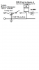
So... you have a 12V source, and an LM7805 regulator.
The regulator will be dropping 7V across is, and will have 500mA (made this number up for this example) passing through it.
This means that the regulator will be dissipating 7V x 0.5A = 3.5Watts.
Now, if you put the resistor in Parallel, it will have 12V dropping across it, and will allow an undisclosed amount of current through depending on it's value. This will dissipate additional heat, on TOP of the 3.5 Watts that the LM7805 is already putting out.

If you put the resistor in 'series' then the voltage drop across the LM7805 will be reduced by whatever the voltage drop across the resistor is.
In 'total' both will dissipate 3.5 Watts. This is the desired effect.

The only case that a parallel circuit would share the heat dissipation is in a constant current circuit... This would mean that 500mA would go in, and branch across any parallel branch. Your circuit, and vehicle however, is a constant voltage circuit. So Parallel circuits will always mean more current and more power dissipated.
 

FvnnyL3tt3r1ng

Feb 26, 2015
23
Joined
Feb 26, 2015
Messages
23
Circuit works. I get readings of 4.7V off the cathode of the IN4001 when I first turn on the power supply of +13.9v (open circuit). The temperature stays pretty constant in all the components with the circuit open. I tried to get an amp reading but for some reason the lights wouldn't turn on when I connected my Klein meter in series with the +4.7V they just flicked on and wouldn't stay on for me to get a reading. I was worried I may have burned them out but they still work fine..... Any ideas?

Also, during my first test I had a 4700uF cap installed and the 2 amp fuse blew and the cap became very hot. Is this because the inrush of current charging the cap? Did I have it hooked up wrong? There is a white line on it but I couldn't really tell which side was - since the leads are on opposite sides. Nonetheless I replaced it with the 4.7uF as in the schematics and it works to power at least one of three fixtures at this time. I have to do some more soldering before I can test all 3 at the same time...

Edit: I did hook up the cap wrong that was probably blowing the fuse. I re-installed the 4700uF and the reading seems to stay at 5.0V. When I turn on a fixture the voltage drops.....will this pose a problem when I go to hook 3 up in parallel?
 
Last edited:
Top