Maker Pro
Maker Pro

Interesting circuit usb with 2 led lights with different brightness

stspringer

May 10, 2019
116
Joined
May 10, 2019
Messages
116
Hello All,
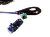
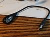
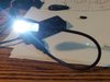
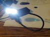
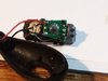
I am intrigued by how this usb, with 2 white leds of different brightness works, can anyone help me understand it. First click turns on first lower intensity led, second click turns on 2nd led with greater intensity, 3rd click turns off both led's.
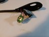
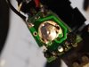
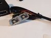
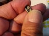
Notice the small metal disk with the dimple on it in pic2.
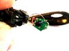
The metal disk, with the dimple, completes the circuit and pops back "rebounds back" after every click. The metal disk dimple is depressed by the plastic nipple seee pic9.

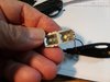
I see the pcb with the tracks.
Can anyone explain how the metal disk completes different circuits?

Does anyone know of a schematic with this same setup?

I purchased this usb led on ebay and took it apart. https://www.ebay.com/itm/JT-2-LED-F...var=502722800566&_trksid=p2057872.m2749.l2649

Thanks
stspringer
 

Attachments

  • usb_2_led_3.jpg
    usb_2_led_3.jpg
    45.4 KB · Views: 15
  • usb_2_led_4.jpg
    usb_2_led_4.jpg
    30.2 KB · Views: 13
  • usb_2_led_5.jpg
    usb_2_led_5.jpg
    31.7 KB · Views: 12
  • usb_2_led_2.jpg
    usb_2_led_2.jpg
    39.2 KB · Views: 14
  • usb_2_led_7.jpg
    usb_2_led_7.jpg
    22.4 KB · Views: 14
  • usb_2_led_8.jpg
    usb_2_led_8.jpg
    27.1 KB · Views: 13
  • usb_2_led_9.jpg
    usb_2_led_9.jpg
    32.5 KB · Views: 14

Bluejets

Oct 5, 2014
6,927
Joined
Oct 5, 2014
Messages
6,927
Metal disc is a form of tactile switch.

If the underside of the board sports a "black blob of tar like substance" then more likely than not, a microcontroller.

There are ways to build up a circuit from discrete components but hey, that's what microcontrollers are for these days.

Although you will not be able to fit it in the same small space.

Arduino is a common choice, connections are simple and in a few minutes a basic program is up and running.

Understanding "manty things at the same time" programming takes a bit to get ones head around but it's a bit like riding a bike or flying a plane.
Once it clicks in the old noggin you have it for ever.

Checkout Jeremy Blum yuotube (one example) videos on Arduino if interested.
 

stspringer

May 10, 2019
116
Joined
May 10, 2019
Messages
116
Hi Bluejets

Metal disc is a form of tactile switch.

I looked up tactile switch it's not mechanical like that, it is just a curved piece of metal that bounces back when clicked on.
like how a clicker toy works.

If the underside of the board sports a "black blob of tar like substance" then more likely than not, a microcontroller.

It obviously makes contact with the pcb but I don't see any tar

[Edited by moderator to clarify quoting]
 
Last edited by a moderator:

Harald Kapp

Moderator
Moderator
Nov 17, 2011
13,727
Joined
Nov 17, 2011
Messages
13,727
That IS a tactile switch
Right! The most primitive form that uses a center pad below the metal dome as the second contact.

Have no idea what you mean by that ?
What @Bluejets refers to is not tar. It is black epoxy. It is common for mass produces inexpensice electronics to use chips without a separate case. Instead the chip is directly bonded to the PCB and protected by a blob of black epoxy.
In this case it seems the epoxy is gray, cf. usb_2_led_8.jpg.
@stspringer : Can you give us a close-up look at that part, or better of both sides of the PCB?
 

hevans1944

Hop - AC8NS
Jun 21, 2012
4,882
Joined
Jun 21, 2012
Messages
4,882
What @Bluejets is saying is the tactile switch (and it IS a tactile switch) completes one (and only one) circuit that is an input bit for a microprocessor. A program in the microprocessor (or μP for short) "reads" and interprets the switch presses and then provides two output bits that turn on and off two LEDs.

It's up to the Asian engineer who designed the contraption how they want to do this, but two levels of brightness require two bits of "data" to implement, and in this case that would be two LEDs. Often the μP can be designed to "drive" external LEDs directly, without the need for additional components. The logic that decides which of those LEDs will be turned on as a result of tactile switch presses is easiest to implement with the logic programmed in a μP.

The cheapest way to implement the μP is to purchase individual dies, with the program "burned in" to a mask that is used to make the customized dies on the wafer when the wafer is manufactured. This is a low-cost, high-volume, process: millions of dies are made at the same time. After circuits are added to the wafer, individual dies are cut from the wafer, sometimes tested for functionality, and then "glued" directly to the printed circuit board. Wire bonds are then welded from PCB landings to pads on the dies. Finally, the entire assembly is coated with a tough plastic material (usually resembling tar) to protect the die and the wire bonds. All this assembly is done by programmable machines, without human intervention after programming, faster than the eye can follow. And this is why such things are dirt cheap.

Tactile switches DO resemble clicker toys. I remember when Texas Instruments was touting their Klixon switch, giving away free samples at trade shows of a bi-metallic disk a bit larger than a nickle coin. You would use body heat or finger friction to heat the disk and then "snap" it into one of two stable positions. Upon cooling to ambient temperature, differential contraction of the bi-metallic disk components caused the disk to "snap" back to its other stable position, usually with considerable force that sent it flying through the air if surreptitiously placed on a nearby table. Lots of fun. Wish I had kept a few.

Anyhoo, TI went on to incorporate the principle into a wide array of thermal switches. And someone else figured out a way to make the disk snap back to a preferred position after pressure was released from the center of the disk. Voila! Snap-action tactile switches were born! These soon found much favor in computer keyboards, where they closely imitated the tactile "feel" of manual and electric typewriters. And of course they are used everywhere today from home appliances to toys to novelty items like your USB lamp. The el-cheapo ones don't last very long because the metal "clicker" is poorly made, eventually loses its "springiness" and quits working. But archeologists will be digging the well-made ones out of the rubble a thousand years from now and wondering just what the heck they were made for.
 

stspringer

May 10, 2019
116
Joined
May 10, 2019
Messages
116
That IS a tactile switch :)
as per your photo


Have no idea what you mean by that ?
see post #2
If the underside of the board sports a "black blob of tar like substance" then more likely than not, a microcontroller.
 

stspringer

May 10, 2019
116
Joined
May 10, 2019
Messages
116
Right! The most primitive form that uses a center pad below the metal dome as the second contact.


What @Bluejets refers to is not tar. It is black epoxy. It is common for mass produces inexpensice electronics to use chips without a separate case. Instead the chip is directly bonded to the PCB and protected by a blob of black epoxy.
In this case it seems the epoxy is gray, cf. usb_2_led_8.jpg.
@stspringer : Can you give us a close-up look at that part, or better of both sides of the PCB?


Will do I will take it apart again and take more pics
 

stspringer

May 10, 2019
116
Joined
May 10, 2019
Messages
116
What @Bluejets is saying is the tactile switch (and it IS a tactile switch) completes one (and only one) circuit that is an input bit for a microprocessor. A program in the microprocessor (or μP for short) "reads" and interprets the switch presses and then provides two output bits that turn on and off two LEDs.

It's up to the Asian engineer who designed the contraption how they want to do this, but two levels of brightness require two bits of "data" to implement, and in this case that would be two LEDs. Often the μP can be designed to "drive" external LEDs directly, without the need for additional components. The logic that decides which of those LEDs will be turned on as a result of tactile switch presses is easiest to implement with the logic programmed in a μP.

The cheapest way to implement the μP is to purchase individual dies, with the program "burned in" to a mask that is used to make the customized dies on the wafer when the wafer is manufactured. This is a low-cost, high-volume, process: millions of dies are made at the same time. After circuits are added to the wafer, individual dies are cut from the wafer, sometimes tested for functionality, and then "glued" directly to the printed circuit board. Wire bonds are then welded from PCB landings to pads on the dies. Finally, the entire assembly is coated with a tough plastic material (usually resembling tar) to protect the die and the wire bonds. All this assembly is done by programmable machines, without human intervention after programming, faster than the eye can follow. And this is why such things are dirt cheap.

Tactile switches DO resemble clicker toys. I remember when Texas Instruments was touting their Klixon switch, giving away free samples at trade shows of a bi-metallic disk a bit larger than a nickle coin. You would use body heat or finger friction to heat the disk and then "snap" it into one of two stable positions. Upon cooling to ambient temperature, differential contraction of the bi-metallic disk components caused the disk to "snap" back to its other stable position, usually with considerable force that sent it flying through the air if surreptitiously placed on a nearby table. Lots of fun. Wish I had kept a few.

Anyhoo, TI went on to incorporate the principle into a wide array of thermal switches. And someone else figured out a way to make the disk snap back to a preferred position after pressure was released from the center of the disk. Voila! Snap-action tactile switches were born! These soon found much favor in computer keyboards, where they closely imitated the tactile "feel" of manual and electric typewriters. And of course they are used everywhere today from home appliances to toys to novelty items like your USB lamp. The el-cheapo ones don't last very long because the metal "clicker" is poorly made, eventually loses its "springiness" and quits working. But archeologists will be digging the well-made ones out of the rubble a thousand years from now and wondering just what the heck they were made for.

Wow, that is truly amazing. Very informative.
Are there resistors in this mix too? Or is that controlled by the mp somehow?
Thank you
stspringer
 

stspringer

May 10, 2019
116
Joined
May 10, 2019
Messages
116
Ok I read this again
"without the need for additional components."
Thanks again

It's up to the Asian engineer who designed the contraption how they want to do this, but two levels of brightness require two bits of "data" to implement, and in this case that would be two LEDs. Often the μP can be designed to "drive" external LEDs directly, without the need for additional components. The logic that decides which of those LEDs will be turned on as a result of tactile switch presses is easiest to implement with the logic programmed in a μP.
 
Last edited by a moderator:

stspringer

May 10, 2019
116
Joined
May 10, 2019
Messages
116
It is black epoxy there it is! pic 2
 

Attachments

  • led_mp_1.jpg
    led_mp_1.jpg
    23.6 KB · Views: 6
  • led_mp_4.jpg
    led_mp_4.jpg
    22.9 KB · Views: 6
  • led_mp_3.jpg
    led_mp_3.jpg
    30.2 KB · Views: 7
  • led_mp_2.jpg
    led_mp_2.jpg
    25.4 KB · Views: 7
Last edited by a moderator:

stspringer

May 10, 2019
116
Joined
May 10, 2019
Messages
116
Can these mp's be purchased? Can we emulate this on a breadboard?
Any schematics?
Thanks
 

hevans1944

Hop - AC8NS
Jun 21, 2012
4,882
Joined
Jun 21, 2012
Messages
4,882
Yep Looks like you found it!

Can these mp's be purchased? Can we emulate this on a breadboard?
Any schematics?
Thanks

You can duplicate the functionality of this lamp with a PIC μP or an Arduino if you want to get your feet wet with programming. This is typically done on a solderless breadboard. As far as schematics are concerned, Google could be your best friend for those. But this is a hobby forum, so most folks here develop their own circuit schematics as part of their hobby.

There is no way that I know of to compete domestically with the low-cost productivity of the Pacific Rim countries though. And if you do come up with a spiffy new software for two "white light" LEDs powered from a USB port, someone "over there" will immediately reverse engineer and steal it. The Asians, especially the Chinese, have absolutely zero respect for laws related to intellectual property protection and either just pay them lip service or ignore them. Same thing occurs here, and it has been going on for a long, long time. The only "solution" I see is to get in quickly, sell enough of your unique niche product to cover your development and initial production costs plus a small "profit," and then move on to something else after the competition counterfeits it.
 

Bluejets

Oct 5, 2014
6,927
Joined
Oct 5, 2014
Messages
6,927
Take a few hours off and watch some ( at least) of the Jeremy Blum youtube videos on Arduino .
Start at No.1 and work your way through.
Don't be too concerned if the penny doesn't drop right off as you can go back again as many times as it takes.
Thing is to watch it all first and then get a few "clone" bits ( as they are much cheaper and work ok) and "give it all a go" and if you get hung up, go back and watch THAT video again.
You will find there is plenty of help for those who try and don't do so well, none though for those who do not try. (Arduino forum one of many)
 

hevans1944

Hop - AC8NS
Jun 21, 2012
4,882
Joined
Jun 21, 2012
Messages
4,882
I must strongly agree with @Bluejets suggestion to @stspringer to use Jeremy Blum's videos to learn about the Arduino, how to use it, and how to program it. This series of videos is very much the 'hands-on" approach to learning, and the "how" of it is explained very clearly with excellent videography, well composed and in-focus. The episodes I viewed (I didn't view all of them) often were skimpy on "why" Jeremy did things the way he did, but his methods worked so, as they say, it is left as an exercise for the student to figure out exactly why they worked. Logic that works is understandable by anyone who understands logic, but it isn't always obvious at first glance. Learning how to use Arduino requires the same dedication that would be required to receive an invitation to perform at the New York Metropolitan Opera: Practice, practice, practice.
 

Wollowstone

Mar 26, 2018
18
Joined
Mar 26, 2018
Messages
18
Could be based on a shift register used as a circular buffer with the "click" playing the role of a clock edge signal. Part of the problem could be to initialize the original state of 0s and one 1.
 
Top