Maker Pro
Maker Pro

Just finished my first project!

cheesysam

Jan 10, 2010
9
Joined
Jan 10, 2010
Messages
9
Hi all, nice to meet you.

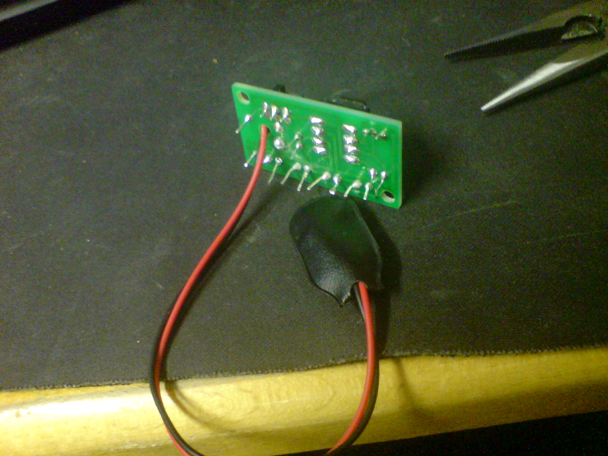
I recently found an interest in electronics so I bought a basic project kit from Maplin. Nothing fancy, just 4 LED's that flash. I thought I'd share the finished article with you, not bad first solders eh? Although I couldn't clip the component legs as much as I would have liked. Any tips for how to get in between the gaps?

I've got an electronic dice to do next, watch this space!
 

cheesysam

Jan 10, 2010
9
Joined
Jan 10, 2010
Messages
9
LCXpy.jpg


IsoOC.jpg
 

Resqueline

Jul 31, 2009
2,848
Joined
Jul 31, 2009
Messages
2,848
Welcome!
Surely as nice as my first joints, iirc..
What flash pattern does it have, and what's the kit description?
You'll need a dedicated electronics wire cutter - other than the needle-nose pliers you got there.
 

cheesysam

Jan 10, 2010
9
Joined
Jan 10, 2010
Messages
9
Hi Resqueline,

Thanks for the warm welcome!

The kit title is 'LED Battery Saving Lamp'. I got it for about £3.99 I think. It was brighter than I expected. I'll have a look for some proper wire cutters :)

If I understand your question correctly, its flashed in a 555 configuration. Is that what you meant? I've been meaning to draw out the circuit so i can properly understand what's going on. I don't (yet) know any more than it has to be a full circuit to work :p I know the purpose of resistors but that's about it.
 

Resqueline

Jul 31, 2009
2,848
Joined
Jul 31, 2009
Messages
2,848
Yes, good LED's can be surprisingly bright.
Ok, I see. They are all series-connected and then the 555 makes them blink briefly (like a bike rear lamp).
Have a look around here. There are some threads that are very detailed & basic, good for learning.
 

Graham

Nov 10, 2009
30
Joined
Nov 10, 2009
Messages
30
Way to go Sam. Nice job!
I cut my teeth on an electronic dice circuit many years ago - then gradually progressed through Sinclair ZX80 and UK101 'computer' kits (that should give some hints about my age), and then designed and built a few circuits of my own (that's when I got the Microtest 80 meter Resqueline... funnily enough - I'm still using the same soldering iron I used on those projects too).

Try to keep your first projects simple in scope so you can break the circuits down into logical blocks and understand the basic operation of the circuit - you don't have to understand what every last component does just yet ;)

Keep at it, and it'll all start dropping into place.
Graham
 

cheesysam

Jan 10, 2010
9
Joined
Jan 10, 2010
Messages
9
Hi Graham, nice to meet you.

I finished the electronic dice a couple of days ago and it works like a charm :) Again it was a lot better than I expected. I'll post some pictures when I get round to it.

I have a ZX Spectrum somewhere too, not a kit model though.

I was trying to work out the 555 circuit and what was happening, although didn't make much progress. All the sites I looked at about it were fairly in-depth. Too many pins confused me. I think I need to look at the VERY basics. Although I'm starting to learn the resistor colour codes quite well, I consider that good progress :)
 

Graham

Nov 10, 2009
30
Joined
Nov 10, 2009
Messages
30
Hi Sam,
OK - let me try and explain a really basic 555 astable (constantly cycling on and off) circuit... This circuit uses the 555 chip, a couple of resistors, and a capacitor. Here's the schematic for the circuit I'm describing... Don't worry about all the technical stuff on that page, just try and follow my description on the diagram.
http://www.kpsec.freeuk.com/555timer.htm#astable

Firstly, think of the chip itself as being divided into 3 parts - part one just sits there and monitors a voltage (via pins 2 & 6), part three (coincidentally pin 3) is the output voltage that drives the rest of your circuit (in your case, the 4 LEDs - it may not be powerful enough to do this on its own - so you may have some additional components on your board to help with that, but they are nothing to do with the astable circuit). Part two sits in the middle and is basically just a couple of switches.

To start with, the voltage runs through the two resistors (R1 & R2) and starts charging the capacitor (C1). Part one of the chip is watching the voltage on that capacitor as it starts to charge up. When it gets to a certain level (about 2/3 of +Vs, where +Vs is your supply voltage), it gives part two a nudge and says "hey buddy, flip your switches... NOW!".

Now, one of those switches connects your output (pin 3) directly to supply voltage (+Vs) on pin 8 - in other words, the output is switched on and your LEDs light up - yay!! At the same time, the other switch connects the discharge pin (pin 7) to the 0v side of your circuit on pin 1. This effectively routes the voltage that was charging the capacitor through a much easier route of just one resistor and then straight to 0v (you remember that electricity will always find the easiest route through a circuit - the famous "path of least resistance"). This removes the voltage from the capacitor, and stops it from charging.

When the voltage is removed from the capacitor, it starts to DIScharge what it has stored in it (I guess that's why pin 7 is called the discharge pin), and the voltage now starts draining out of the capacitor. Remember pins 2 & 6? Well, they are still monitoring the voltage, except now it is falling instead of rising. When the voltage falls to a certain level (about 1/3 of +Vs), it gives part two a nudge again and says "hey buddy, flip those switches back will ya?".

So the output pin 3 is disconnected from +Vs (not sure if it is switched over to 0v instead or just left disconnected - probably the former - but that's not too important here) and your LEDs switch off - boo hoo. The other switch gets flipped as well, and that forces the electricity to go back though the harder route of both resistors and into the capacitor again. Guess what - that means it starts charging again, and the voltage starts to rise. Pins 2 & 6 are still sitting there, watching and waiting till the voltage reaches 2/3 +Vs, and so the process goes round again - on... and on... and on... and... you get the picture.

So that's roughly how it works (note I say "roughly" before anyone starts flaming me for any inaccuracies). The other thing to know is that by changing the values of those two resistors and the capacitor, you can control the frequency of your LEDs flashing, and also the amount of time in each flash that they are on and off. I won't go into all the maths and physics around that - partly because there are a million online calculators that will work out what you need to achieve any given result, and partly because I don't understand it either :D

So there you go - you (hopefully) now understand your first circuit - sorry it took so many words to describe :rolleyes: and apologies to all those that understand circuits far better than me, and can spot a million flaws in my description. There are many variations and elaborations on this most basic astable, and you may well have a few other components though looking at your picture again, I think I only see one extra resistor, which is probably just to control the current flowing through the LEDs (here's a link to a good resource for calculating the value of resistor to get an LED to light correctly even when it is connected to the wrong voltage http://www.theledlight.com/ledcircuits.html
)
All the best, and good luck

Graham.
 

cheesysam

Jan 10, 2010
9
Joined
Jan 10, 2010
Messages
9
Wow Graham, that response was superb. Thanks for going to the trouble of typing that up for me, I really appreciate it. And the icing on the cake is, this genuinely makes more sense to me now.

I'm going to have a go at reproducing the 555 on my new breadboard and see if I can start changing the components for different results. I'll have a look for one of those online calculators you mentioned.

I'd looked into what a capacitor does and didn't really understand why that would ever be of any use, but I see now how useful they are.

Thanks again mate!
 

kyjosh

Dec 15, 2009
65
Joined
Dec 15, 2009
Messages
65
They certainly look better than my solder points. I am the world's worst solderer. Others would cringe if they saw my metallic mutilations. LOL

Using a 555 in an astable circuit like that, you can also add a 4017 IC to sequence the pulses. That would let you light up LED1 then LED2 then LED3 and restart, or hook them up in a few different patters depending on which outputs you use. The 4017 is a decade counter so it counts clock pulses ten times. You have 9 normal outputs and then an output that goes high when the first four outputs are low. It is limited in the patterns you can make (it isn’t a PIC or anything) but it is definitely fun to play around with.
 

kyjosh

Dec 15, 2009
65
Joined
Dec 15, 2009
Messages
65
Also, a great way to find the resistor needed for an LED is to subract its forward voltage from the source voltage, and then divide that answer by the desired current.

For example, a red LED usually drops 1.7V at 20ma, so when using a 9V source:

9-1.7=7.3

7.3V/.02=365

Taking the closest but higher resistor you would need a 390Ohm resistor to drive an LED off of a 9V source.

The same thing works for series LEDs too, you just add up your forward voltages and then subract that from the source voltage. The trickiest part sometimes is just finding the actual specs on the LEDs you are using.
 

cheesysam

Jan 10, 2010
9
Joined
Jan 10, 2010
Messages
9

I'll tell you what Graham, I'm over the moon. All thanks to you that is :p Took a lot of swapping resistors around, and I could only get the red LED to light up more brightly than the other or not at all. But at least it works.

Apologies for (very) amateur photography.
 

Graham

Nov 10, 2009
30
Joined
Nov 10, 2009
Messages
30
Nice one Sam!! You are obviously experimenting away there - so now you have your astable 555 circuit driving alternate LEDs? Keep going and trying out new things - I can feel your excitement from here!

Now, with your red and yellow LEDs, indeed with all different colour LEDs, they each use a slightly different voltage and current. Your standard red LED is the 'cheapest' in terms of voltage and current, which is why they are so prevalent in devices that have a standby mode.

So, to get a red and yellow LED alongside each other to light up with the same apparent brightness, each will need to have a dedicated resistor, and the two resistors will be different values to 'tune' the circuit to deliver the optimum juice to the LED. So for a traffic light effect, each of the red, amber and green LEDs would need its own resistor, and you would need to do 3 calculations to find the correct values for each one. I'm guessing your problem is that you are driving both LEDs either with a common resistor, or two resistors the same value?

Check out this page - if you scroll down to the last circuit, it shows a simple setup with a mix of red and blue LEDs and the resistors for each.

Cheers,
Graham
 
Top