When I pressed the switch i can't get any O/P from the keypad(apart from program in controller,checked with multimeter also).
Is this circuit is correct or have to make any change in this circuit..?
RB0 and RB1 should supply a logic 1 to their respective resistor packs (2 lots of 5 resistors) and each bank of 5 switches should pull RB2 to RB6 respectively to ground.
Your schematic drawing convention is particularly 'disturbing' and makes for incredibly difficult understanding.......
RB0 and RB1 should supply a logic 1 to their respective resistor packs (2 lots of 5 resistors) and each bank of 5 switches should pull RB2 to RB6 respectively to ground.
Your schematic drawing convention is particularly 'disturbing' and makes for incredibly difficult understanding.......
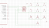
Now see in this image.I maked RB0 to RB6 as pulled up pin using resistor RN1 with 1k.
When I pressed S1 means RB0 and RB3 will become low state.Similiary it will work for all remaining buttons...By this method can interface keypad to the controller..?