Maker Pro
Maker Pro

LDO gets hot when using a relay module?

BucketOfFish

Oct 6, 2015
9
Joined
Oct 6, 2015
Messages
9
Hi everyone,

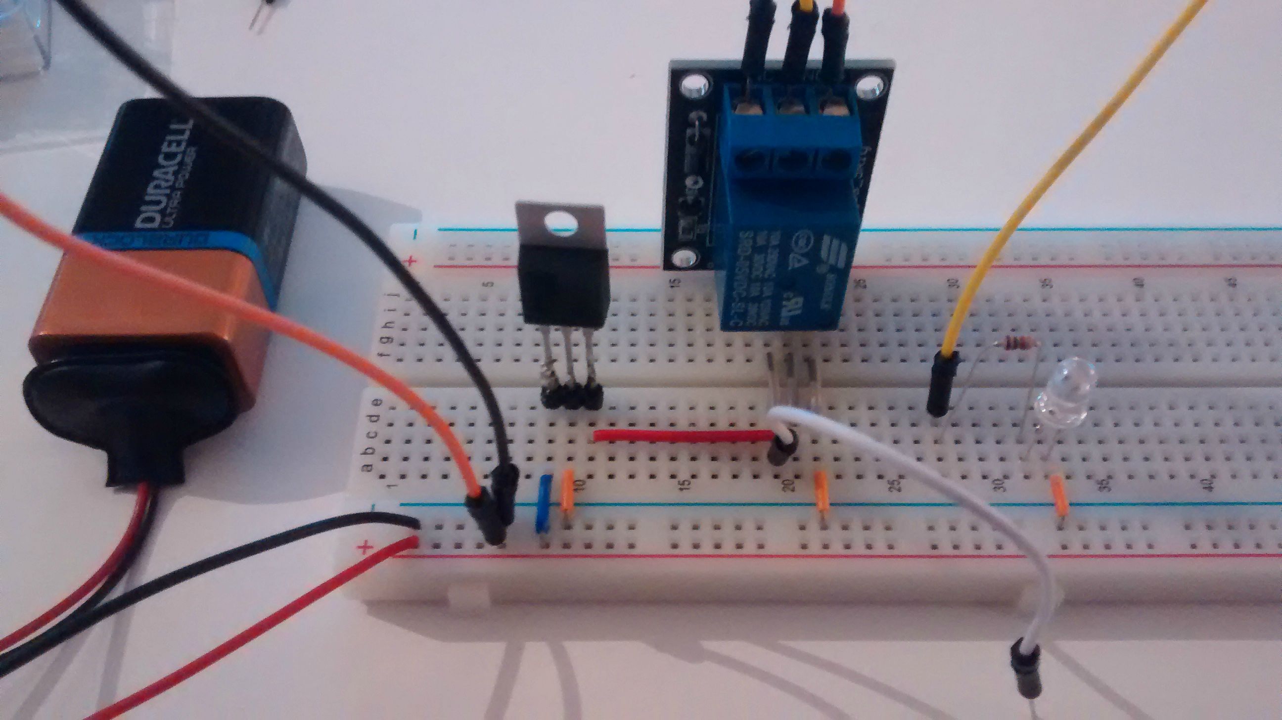
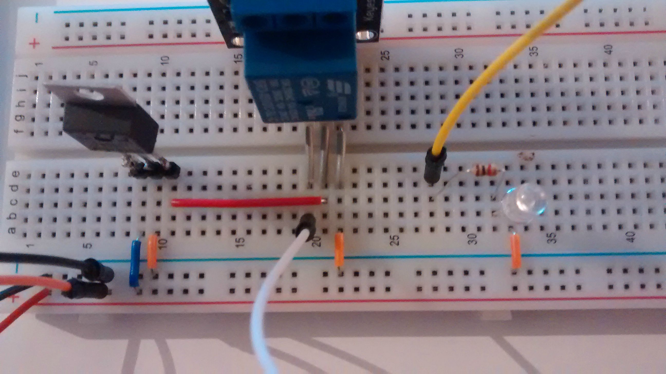
I have a question about the attached circuit:

QOoPLfw.jpg


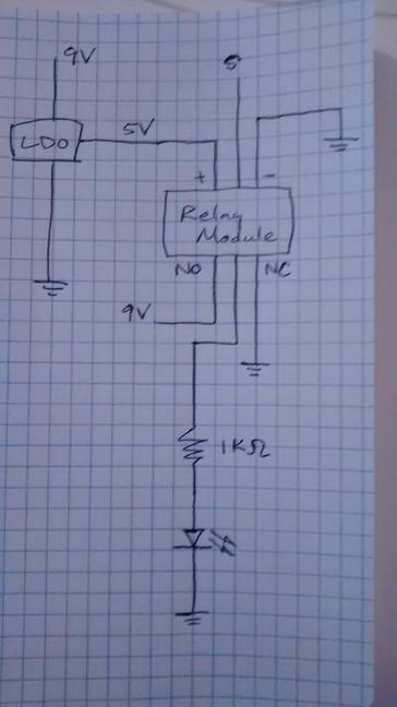
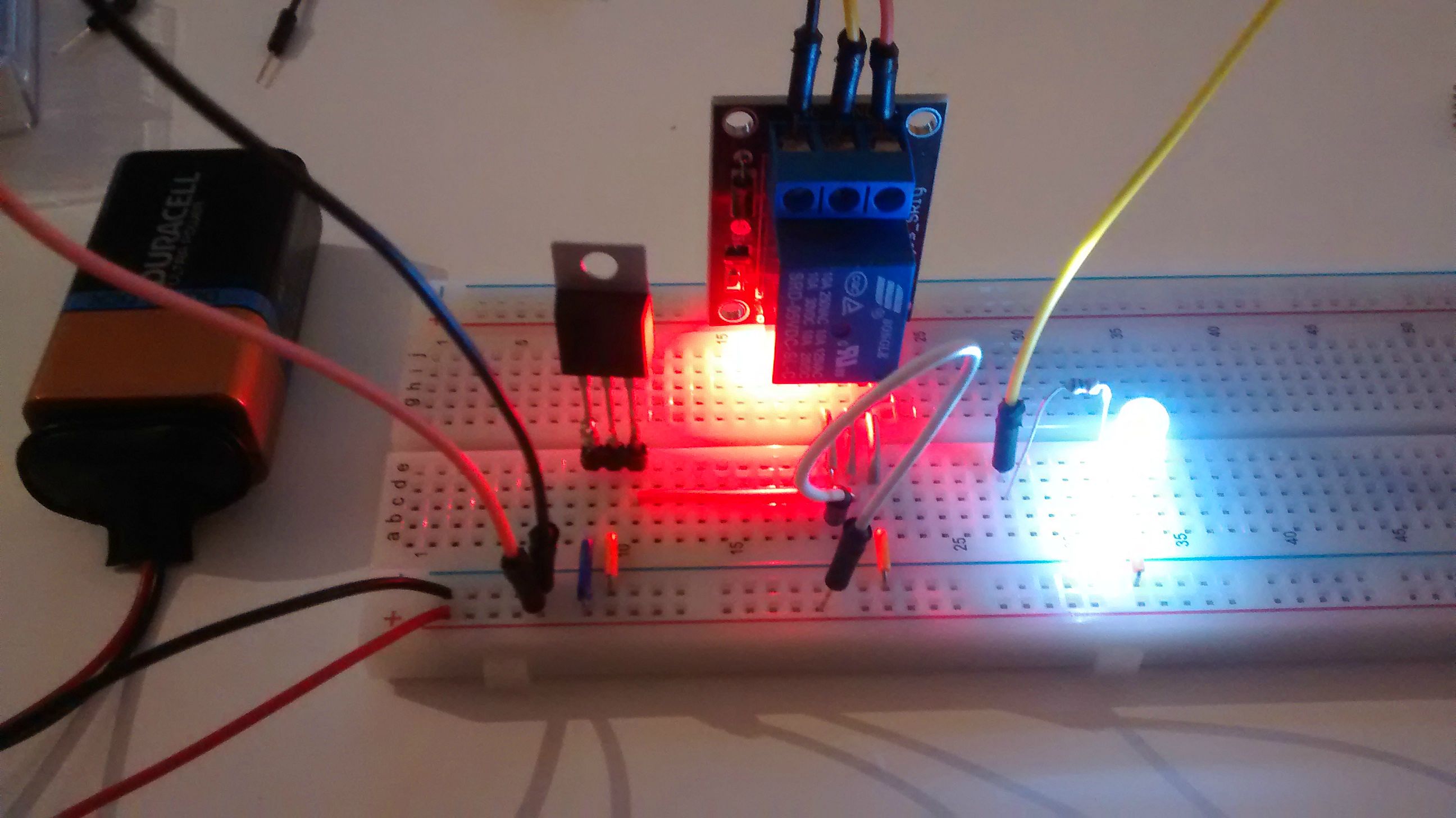
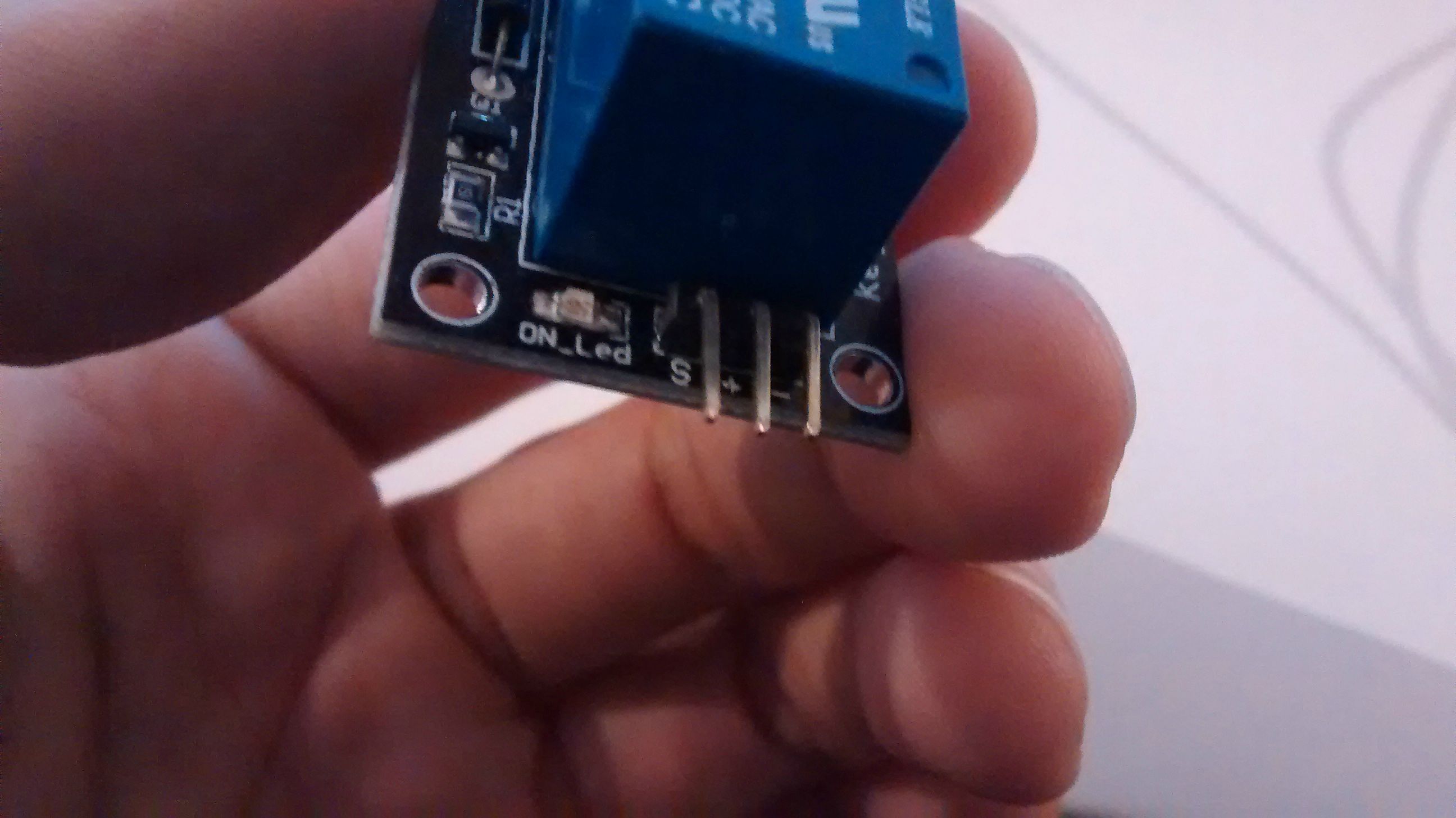
(Sorry if it's unclear - I have very little experience in drawing circuit diagrams). What I have here is a 5V relay module powered by a battery, with an LDO providing the 5V input to the relay. When the signal (S) pin is low, the module and LED are off. When S is high, the module and LED are both on.

My question is this - when the module is on, after a while the LDO gets hot. Why is this? I figure I probably need to add another resistor somewhere, but where is the best place?
 
Last edited:

Tha fios agaibh

Aug 11, 2014
2,252
Joined
Aug 11, 2014
Messages
2,252
QOoPLfw.jpg
I figure I probably need to add another resistor somewhere, but where is the best place?
I think you need to limit the current into the relay so devide 5v by the required coil current to get resistor value and put it in series between ldo and relay coil. Also add a blocking diode parallel with coil to mitigate spikes.
 

(*steve*)

¡sǝpodᴉʇuɐ ǝɥʇ ɹɐǝɥd
Moderator
Jan 21, 2010
25,510
Joined
Jan 21, 2010
Messages
25,510
The problem is likely that the current required to operate the relay is quite high and the power dissipation in the regulator is such that its getting hot.

I will assume that your reason for using a relay is more than just to turn on and off a LED, so I won't comment on that.

The first thing is to calibrate your finger so we have a good idea of how hot the regulator is actually getting. Look for this resource (sorry its hard to insert a link from a mobile platform) and let us know how hot it actually is.

if it is too hot then the options include using a relay with a lower operating current, using a physically larger regulator, attaching a heatsink to the regulator, or using a switch mode regulator (or even a combination of these).

of course the problem may also be that you have a writing error, but if the circuit operates then this is less likely.

The suggestion above to place a diode across the delay coil is one to be followed.
 

dorke

Jun 20, 2015
2,342
Joined
Jun 20, 2015
Messages
2,342
Let us start from the beginning:
What is it that you wish to make/do ?
 

BucketOfFish

Oct 6, 2015
9
Joined
Oct 6, 2015
Messages
9
Hi everyone,

Thanks for your answers! I'm a beginner at electronics, and I'm just learning how to use some of the components which came in a kit I bought. That's why I'm using a relay to switch on an LED, which as some of you noted, is a completely ridiculous application. Placing a resistor and diode in between the LDO and relay makes sense, but I have two questions:

1. Where is the current flow actually going? When the relay switches on, does current flow between the + and - terminals, aka from 5V to ground?

2. How precisely does a 5V relay need a 5V difference between + and -? I would think that placing a resistor between the LDO and relay would cause a significant voltage drop, so I wasn't sure if this was good practice. That is to say, if the internal resistance of the relay is not enough to limit current flow to a reasonable level, wouldn't putting a 1k resistor in series drop the + terminal input from 5V to something more like 2V?

Thanks again for the answers!
 

Tha fios agaibh

Aug 11, 2014
2,252
Joined
Aug 11, 2014
Messages
2,252
Placing a resistor and diode in between the LDO and relay makes sense, but I have two questions:

1. Where is the current flow actually going? When the relay switches on, does current flow between the + and - terminals, aka from 5V to ground?

2. How precisely does a 5V relay need a 5V difference between + and -? I would think that placing a resistor between the LDO and relay would cause a significant voltage drop, so I wasn't sure if this was good practice. That is to say, if the internal resistance of the relay is not enough to limit current flow to a reasonable level, wouldn't putting a 1k resistor in series drop the + terminal input from 5V to something more like 2V?

Thanks again for the answers!

My post hinged upon the fact that the ldo and relay were properly selected.
Current is always the same in a series circuit. That is, at all points in the circuit.
By adding a resistor, it limits the amount of current in the entire circuit (ldo included). So the resistor would help limit current (not voltage) but the relay coil would still need its minimum current.

The conventional current is from + to minus (ground) and the way the arrows point In components like diodes. Technically, current actually goes the other way.

The 5v is what's required to energize the relay, it is not critical, and could probably vary about 20%. (Just a guess)
Adding a resistor in series will limit the current but not the voltage.
The other guys were on point, that the ldo is probably not the best choice in this type of citcuit. The voltage varying is not that critical in a relay circuit.
 

BucketOfFish

Oct 6, 2015
9
Joined
Oct 6, 2015
Messages
9
Hi, I tried out putting a resistor between the LDO and relay, and the LED doesn't light up now when signal is high. I think the voltage concern is valid - measuring resistance between + and - when the relay is on, I see a near-zero resistance. Thus, when any resistor is placed in series with the relay, it ends up taking most of the voltage drop. Even a 100 ohm resistor causes the relay to stop working. This is a bit troubling, because it seems like the relay only works when it essentially acts as a short between 5V and ground! I can't seem to work out a resistor pattern which maintains a 5V difference across the relay terminals and also puts a cap on current. Do I need to use a current source with this thing?
 

dorke

Jun 20, 2015
2,342
Joined
Jun 20, 2015
Messages
2,342
BucketOfFish,
Could you please take a good photo of the relay both from the writing and the "legs" and post it here?
it may clarify things.
 

BucketOfFish

Oct 6, 2015
9
Joined
Oct 6, 2015
Messages
9
Sorry for the size of the following images. Here are shots of the circuit below, without a resistor between LDO and the relay. The LDO pins go from left to right: Vin, GND, Vout. The relay pins go: signal, +, -. The wires coming out the top of the relay are: NC, center, NO.

piNhfeU.jpg

JklHbso.jpg

HM2Uypd.jpg


The relay itself looks like this:

qP306wr.jpg

Fzux3Ne.jpg
 

dorke

Jun 20, 2015
2,342
Joined
Jun 20, 2015
Messages
2,342
The relay is srd-05vdc-sl-c from songle
As can be seen it's coil resistance(nominal) is 70 ohm and the coil current is71.4mA
Nominal voltage is 5V but it can be operated down to 75% pull-in that is 3.75V
srd-05vdc-sl-c.jpg

The relay as 5 "legs", not 6 as your original drawing shows !
2 for the coil
3 for the the contacts,a very basic SPDT configuration
(1 common,1 normally closed and one normally open)

relay.jpg

The power dissipation of the LDO driving the coil is thus about (9-5)*71.4mA=0.285W
Which LDO are you using?
 

(*steve*)

¡sǝpodᴉʇuɐ ǝɥʇ ɹɐǝɥd
Moderator
Jan 21, 2010
25,510
Joined
Jan 21, 2010
Messages
25,510
ok, there's a lot to comment on...

firstly, the suggestion about the resistor requires that you place it in the right place and it has the correct value. I suggest that you skip using a resistor for the moment, but if you were to use one, there are two possible ways to use it. The first is in place of the regulator, the second is between the 9v source and the regulator. In both cases you need to know the likely range of input voltages, the current required, and (if you retain the reg) the dropout voltage of the regulator.

The next issue is the regulator you're using. You describe this as an LDO regulator and these are known to be unstable in certain cases. I note from the recent photos that you do not have any input or output capacitors connected to the reg. You need to connect a pair of 0.1uF caps one between the input and ground, and the other between output and ground.

The next issue has slipped my mind while waffling on about the previous ones. :)
 

dorke

Jun 20, 2015
2,342
Joined
Jun 20, 2015
Messages
2,342
Recalculating the LDO power disipation
The max module current is about 85mA(from the data steve posted)
it agrees with the following:
71.4*1.1 (nominal coil current +10%) +3.5/1k(on borad red led)=82mA

Pd(LDO)=4*82mA=0.33W.

The funny thing is the board already has the LED to turn on...:rolleyes:
 
Top