Maker Pro
Maker Pro

LED's to MUSIC in car stereo or amp Circuit PROBLEMS (BEGINER) please help......!!!!

robikaz

May 19, 2011
7
Joined
May 19, 2011
Messages
7
Scheme.jpg

http://s2.postimage.org/9jmw41gdr/Scheme.jpg

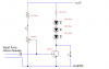
This is my scheme... I guess it's correct, but it still doesn't work....

I connected the AUX in my amp, cause when I connected it to stereo Line-out it didn't worked also...

In my car it's correct, checked so many times

Also, I tried it with potentiometer of 10k and res of 1k....
Now its 1K VR and 10k res...

Please help, I'm trying it from so long now, and have no more Ideas....

Maybe BD241 isn't supposed to work on car stereo or car AMP AUX.... ?
If so, what other transistor or components I should use... ?
 

poor mystic

Apr 8, 2011
1,074
Joined
Apr 8, 2011
Messages
1,074
Hi Robikaz (large smile)
Here's the circuit diagram I would have liked the manufacturer to show me. I hope it's accurate, I do make errors...
The first thing to ask is what happens when you work the switches please?
I'd like you to give me 4 answers. Unplug the input from the amplifier first, please.

1) Both switches off. What are the led's doing?
2) One switch on, the other off. What are the led's doing?
3) Other switch on, first switch off. What are the led's doing?
4) Both switches on. What are the led's doing?

And, do you have a voltmeter?

We'll soon get this sussed.

Mark
 

Attachments

  • revision.png
    revision.png
    13 KB · Views: 2,299
Last edited:

duke37

Jan 9, 2011
5,364
Joined
Jan 9, 2011
Messages
5,364
It looks to me that it should work.
Have you got a voltmeter? There should be 12V across the E-C on the transistor with the leds unlit or about a volt with them lit.
When the potentiometer is turned up the B-E voltage should rise to 0.6V and the leds should light up.
Turn the pot down so the leds just glimmer, then connect a signal. Do they light fully?
The BD241 looks suitable
 

robikaz

May 19, 2011
7
Joined
May 19, 2011
Messages
7
Hi...
I don't have Voltmeter, thats' makes me nervous, cause I know that there should be those 0.6 V, but I can't test it and don't know is everything correct.

1) LED's off
2) Ground switch on - LED's lights on
3) Switch from +12V on - nothing happens
4) Both on - LED's lights on (because of the ground switch is on LED's than gets fully plus and minus from battery)
 

robikaz

May 19, 2011
7
Joined
May 19, 2011
Messages
7
made a new scheme, that does something, don't know why...
Look at this:
5843d1306857634-car-led-music-line-out-electric-scheme-help-beginer-scheme-potentiometer-working.jpg


Added 1k res in lead from AUX (+) to CAP 1uF and, also, connected potentiometer from AUX (+) with same 1k res

That made one trick... with no music (or with music - no different) when turned potentiometer a bit, lights got alltime on.. No dim or bright, just normal turned on... About couple degrees less and it turns off... No mater how much I turn it lights gets on the same bright... But there is one point, where only one degree clockwise and id just turns of

That's funny, but I now know, that 10k VR and BD241 works... And that makes me very HAPPY... No I want to work on project again ;]

Please help guys...
 

robikaz

May 19, 2011
7
Joined
May 19, 2011
Messages
7
Hi guys... No answers yet, so impatiently bought voltmeter today....
Write what should I test ;]
 

poor mystic

Apr 8, 2011
1,074
Joined
Apr 8, 2011
Messages
1,074
Hi again Robikaz
I should have put "S1" and "S2" on the switches. It would make it all so much easier now.

Let's switch the right-hand switch in my drawing "off". Let's leave it off now that we know the led's work, and concentrate on the other switch, which we'll call the base bias switch.

Switch the base bias switch "on" and work the potentiometer with no music going to the unit. Very carefully measure the voltage on the base of the transistor with the pot turned fully each way, and report back what the range of voltages is.... I need to know the highest and lowest voltages that you get on the transistor.

You need to take care not to go shorting things out with your meter probe, a trap for young players.
 

robikaz

May 19, 2011
7
Joined
May 19, 2011
Messages
7
thanks for that:
you were right, we need to communicate faster ;]
here is my skype:
robke999321
add me ;]
 

robikaz

May 19, 2011
7
Joined
May 19, 2011
Messages
7
At this scheme potentiometer works :
schemepotentiometerwork.jpg


Tested with voltmeter:
While VR turned to off position, the transistor Base - Emitter showed 0.01
While VR turned to max, transistor Base - Emitter showed 0.73 and LED's lighted
While to less than mid position, when LED's still lighted fully tested Base - Emitter and got results of about 0.2 Voltage...
That means, that transistor needs only about 0.2 volts to Base to light up LED's
 
Last edited:
Top