Hi,
I have seen many P-mosfet based linear current sources but these are for small current more over the main dissipating components is mosfet not resistors.
But now
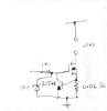
I am looking for p-mosfet based 10A linear current source circuit in which major dissipation component would be resistor.
regards
I have seen many P-mosfet based linear current sources but these are for small current more over the main dissipating components is mosfet not resistors.
But now
I am looking for p-mosfet based 10A linear current source circuit in which major dissipation component would be resistor.
regards