Maker Pro
Maker Pro

LM7805 - Linear Voltage Regulator And DC-DC Converter Analysis

Integrator741

Jun 16, 2013
125
Joined
Jun 16, 2013
Messages
125
Hello,

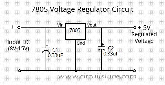
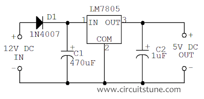
I am trying to find some information about "Voltage Regulator" and "DC-DC converter" circuits. Things like how do they work? Component analysis and purpose of the LM7805 IC in the circuit.

Voltage Regulator
7805-Voltage-Regulator-Circuit-Diagram.jpg


DC-DC Converter
12-to-5-volt-dc-to-dc-converter-circuit-diagram.png


If somebody would give me some bits and peaces I would be really thankful :)

Thanks,
Integrator
 

BobK

Jan 5, 2010
7,682
Joined
Jan 5, 2010
Messages
7,682
The 7805 is a linear voltage regulator. It samples the output voltage, compares it to a reference voltage and then adjusts a pass transistor to keep the output voltage at 5V.

Bob
 

(*steve*)

¡sǝpodᴉʇuɐ ǝɥʇ ɹɐǝɥd
Moderator
Jan 21, 2010
25,510
Joined
Jan 21, 2010
Messages
25,510
This almost sounds like homework...

If you google for LM7805 you wull find links to various manufacturers datasheets which will describe all you need in eye-watering detail.

Have a look and see what you can understand. If you have more questions, tell us what you're stuck on and we'll try to point you in the right direction.
 

Integrator741

Jun 16, 2013
125
Joined
Jun 16, 2013
Messages
125
OLIVE2222 - Thank you for the data sheet, that was very helpful :)

Okay so I got that C (input) is required to prevent oscillation and reduce power supply ripple;

C (out) is for phase compensation of the internal error amplifier.

So are those capacitors doing the same job in two different circuits?
 

davenn

Moderator
Sep 5, 2009
14,260
Joined
Sep 5, 2009
Messages
14,260
..................

So are those capacitors doing the same job in two different circuits?

sort of

For whatever reason the low value cap has been left out of the input to the regulator in the second circuit
there should still be a cap of ~ 0.1 TO 0.47Uf in parallel with the 470uF
The 470uF will only help with ripple reduction, it wont have much effect on the oscillation stability issue as its value is too big

Also ... if running off a battery supply, there not a lot of requirement for a high value cap on the input, as the ripple will be 0V

Dave
 

JimW

Oct 22, 2010
59
Joined
Oct 22, 2010
Messages
59
From what the original poster put in the title and the labels of the two circuits, there is a bigger misunderstanding here. Both circuits use the same IC, both are linear voltage regulator circuits. The values of the caps are generally not differentiating the two from each other.

A DC-DC converter circuit is a whole different beastie. You did not include a drawing of one. What is does is take a DC input, change it to a high(-ish) frequency AC signal, increase or decrease it using an inductor or transformer, and then filter it back to a DC voltage (where the final voltage is generally controlled by the pulse width and separation of the AC part of the circuit). Google "DC Converter IC" and you will get more information and some sample circuits.

JimW
 
Top