Maker Pro
Maker Pro

Marantz SM500DC - defective

eytonbranhan

Oct 12, 2019
53
Joined
Oct 12, 2019
Messages
53
Hello,

I have a Marantz SM500DC (power amplifier) but it doesn't work and I don't know why...

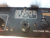
When I push the power button, there is no light on the front (maybe it's just the light bulbs that are broken...).

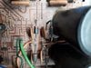
I unmounted the SM500DC to do a visual check and nothing seems to be broken.

I checked all the four power transistors and they are OK (continous tests, Diode tests).
I also checked that there is 68V on the P700 electronic board and this is the case.

So I decided to plug an audio source into the Input L & R" connectors but there is no sound that comes out on the System 1, System 2 and even in the headset connector.

Does anyone could help me please ?

Thank you in advance.

Best regards,

Eyton
 

Ylli

Jun 19, 2018
405
Joined
Jun 19, 2018
Messages
405
Service manual here: https://www.hifiengine.com/manual_library/marantz/sm500dc.shtml

Where are you seeing 68 volts? I see rail voltages of +/-46 volts.
Are all the fuses good, including F801? F801 feeds the lights, which look to be 6 bulbs in series.

Most likely, the protection circuit is active and the protection relay is not pulled in. Confirm the rail voltages and then we can troubleshoot the protection.
 

eytonbranhan

Oct 12, 2019
53
Joined
Oct 12, 2019
Messages
53
Hello Ylli,

Thank you for your reply !

I see 68 Volts (AC) between J806 and J807, the two orange cables that come from the transformer.


For the light, it doesn't work but I can measure 8V on each one.

I'm not sure to know what is the rail voltages.
I think I need to measure the voltage between the ground and the junction of Q803 and Q804 ? is it correct ?
And also between the ground and the junction of Q801 and Q802 ?

For the fuses, I'm not sure too. I only saw one fuse, the main one... is it the fuse called F801 ?


This fuse is OK, I tested it again.
If it's not the F801 fuse, I really don't know where is this last... : /
Is there other fuses on this Marantz ?

BR,

Eyton
 

Attachments

  • 20191012_194422.jpg
    20191012_194422.jpg
    133.5 KB · Views: 10
  • 20191012_195217.jpg
    20191012_195217.jpg
    69 KB · Views: 4
  • 20191012_195228.jpg
    20191012_195228.jpg
    62.1 KB · Views: 4
Last edited:

Ylli

Jun 19, 2018
405
Joined
Jun 19, 2018
Messages
405
Hello Ylli,

I see 68 Volts (AC) between J806 and J807, the two orange cables that come from the transformer.
OK, that is correct.
For the light, it doesn't work but I can measure 8V on each one.
Strange - the schematic shows the lamps in series, but the board layout shows them in parallel. If they are in series, then if one burns out, they all go out. In parallel each is independent. F801 is a fuse in the line driving the lamps, but if you see 8 VAC on the lamps, then that fuse would be good. Can you confirm with your ohmmeter (power off) that the other side of the lamps go to ground?
I'm not sure to know what is the rail voltages.
I think I need to measure the voltage between the ground and the junction of Q803 and Q804 ? is it correct ?
And also between the ground and the junction of Q801 and Q802 ?
Yes, but these voltages are also on the collectors of the output transistors and those points may be more accessible. BE CAREFUL, there is lots of energy at these points. Do not short them to anything else when trying to measure.
For the fuses, I'm not sure too. I only saw one fuse, the main one... is it the fuse called F801 ?
No, F801 designator is located just left of the power transformer leads in your picture. It is either installed on the bottom of the board or is not installed. In either case, if you are getting +8 up to the lamps, then it is not an issue.

Now on to the main issue.
Assuming the rail voltages are present and near nominal voltage (+/-46 volts), let's measure both channels for output offset voltage. With your voltmeter negative lead on chassis ground, measure the voltage on the center terminal of R741 and R742. These resistor generally look like white rectangular blocks near the output transistors and have three legs - often with those legs extending all the way out the top to act as test points. You want to measure the voltage on the center pin. Caveat about the high energy applies here too. No shorting anything!
Capture.JPG
 

eytonbranhan

Oct 12, 2019
53
Joined
Oct 12, 2019
Messages
53
Many thanks for your help Ylli ! You rockx !

Before going further, I need to be clearer about the light: I measure 8V AC, not DC ...

I think there is something strange with the 24VDC relay.
Should I be able to hear a "click" from the relay when I power up the amp ?
If yes, it's not the case and I checked this relay and found something weird :


Do you think this black dot should be on the relay's coil ?

I also measured the coil and it's 1,35 KOhms
 

Attachments

  • 20191012_211659.jpg
    20191012_211659.jpg
    92 KB · Views: 7
Last edited:

eytonbranhan

Oct 12, 2019
53
Joined
Oct 12, 2019
Messages
53
Yes about the bulbs, the other side of each bulbs go to the ground

measure of both channels :


left's resistor : 0 VDC
right's resistor : -42 VDC
 

Attachments

  • 20191012_220645_text.jpg
    20191012_220645_text.jpg
    139.3 KB · Views: 5

eytonbranhan

Oct 12, 2019
53
Joined
Oct 12, 2019
Messages
53
I don't know what happened but now I have a bulb on !


I just tried to plug the two speakers on the "system 2" circuit instead of one on each
but there is still no sound coming out of the speakers
 

Attachments

  • 20191012_224338.jpg
    20191012_224338.jpg
    64.6 KB · Views: 5

Ylli

Jun 19, 2018
405
Joined
Jun 19, 2018
Messages
405
On the lamps, it sounds like you just have a bunch burned out.
The relay normally would not look like this, but:
right's resistor : -42 VDC
is your main problem.

You said you checked the output transistors, did you check for collector-emitter shorts? We will need to make some voltage measurements on the right power amp. Let's start out with the voltages on the emitter/base/collector of Q718 & Q720.
Capture.JPG
 

eytonbranhan

Oct 12, 2019
53
Joined
Oct 12, 2019
Messages
53
Yes you're right for the lamps, I look at them closely and most have the filament sectioned
I will try to find some 8V 100mA axial bulbs in replacement

About the output transistors, yes I checked that there is no shorts between any pins of each output transistors.

About Q718 and Q720 :

Q718 :
B : 1,15V
C : 43V
E : 0,57V

Q720 :
B : -1,16V
C : -43V
E : -0,58V

But, if we talked about the same "right's" resistor, you wanted to measure Q717 and Q719, correct ?


Q717 :
B : -42V
C : -43V
E : -42V

Q719 :
B : -42V
C : -43V
E : -42V

No shorts found between each pins of Q717, Q718, Q719 or Q720

thank you again for the great help !
 

Attachments

  • transistors_left_right.jpg
    transistors_left_right.jpg
    127.4 KB · Views: 2

Ylli

Jun 19, 2018
405
Joined
Jun 19, 2018
Messages
405
OK, right resistor/left channel :)

Please measure the voltage on both ends of R747.
Capture.JPG
 

Ylli

Jun 19, 2018
405
Joined
Jun 19, 2018
Messages
405
OK, let's back up a stage on the power amp and look at the voltages on Q711, Q715, and Q703, emitter , base, and collector.
 

eytonbranhan

Oct 12, 2019
53
Joined
Oct 12, 2019
Messages
53
OK lets go, just for the fun because I unwelded the relay this morning to check it deeply :


and just before the measure you asked me for, I weld it again to the board, and then, I heard a click from the relay, plugged the speakers and the sound works now !!!

The measures you asked for :

Q711 :
B : 42 (OK)
C : 1,16 (OK)
E : 42 (OK)

Q715 :
B : -42 (OK)
C : -1,13 (OK)
E : -42 (OK)

Q703 :
B : -41 (OK)
C : -1,16 (OK)
E : 42 (OK)

I really don't know what happened with this relay, do you have an idea ?
 

Attachments

  • relay_checking.jpg
    relay_checking.jpg
    76.6 KB · Views: 3

Ylli

Jun 19, 2018
405
Joined
Jun 19, 2018
Messages
405
There is no way a defect in that relay could have caused the output offset voltage of one channel to be at -42 V. I suspect that the +44 volts that you measured on the load end of R747 wasn't there until you probed it. Look very carefully at the solder around the leads of R747 and reflow if you see any cracking at all. But congratulations - if it is now working then mission accomplished! (but do recheck the soldering on that resistor so it doesn't happend again next week).
 

eytonbranhan

Oct 12, 2019
53
Joined
Oct 12, 2019
Messages
53
mmm you're definitively right about all these old dirty welds !
I tried to redo the welds of the R747 and then, it didn't work again !

So I tried to make the measure of Q703 again, and a short moment after I measured between the ground and the base of Q703, the relay clicked again and the sound appeared... I don't know what to think about that... : / do you have an idea ?

By the way, I would like to thank you so much for your help, I appreciate a lot !
 

Ylli

Jun 19, 2018
405
Joined
Jun 19, 2018
Messages
405
My suspicion is that somehow you are loosing the +44 volts that comes from the load end (left side on the schematic) of R747. This +44 volts should show up at the top end of R731, R729, R711 and R709. When the unit is *not* working, please measure the voltage on the emitter of Q711.
 
Top