Maker Pro
Maker Pro

Megajolt shift lights help please.

mini670

Mar 5, 2013
5
Joined
Mar 5, 2013
Messages
5
Hi there,

Im new on here. I have a circuit id like to make up for a project i have on. Im after some help or pointers please.

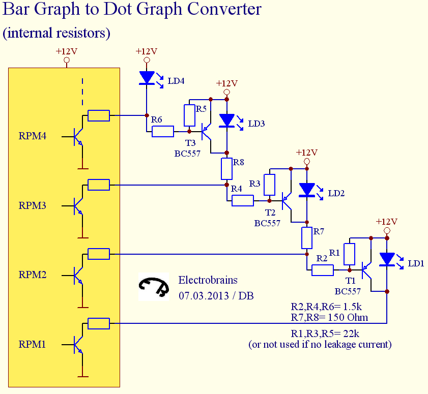
I fitted a megajolt electronic ignition system to my car. It has 5 outputs that can be used as shift lights which light up at a programmed RPM. The LED`s must have constant +ve voltage, when a certain RPM is achieved the megajolt unit grounds that LED out so it is in circuit.
Now this works sequentially so as rpm1 is reached you get a light, as rpm2 is reached you get a second light, rpm3 for third light and so on.

Im after a circuit that switches off all the previous rpm lights as the new rpm is achieved. So as rpm2 is reached rpm1 switches off, as rpm3 is reached rpm2 switches off. ie only one led on at any time.

I think this is possible with relays, but im not keen on using them due to current and moving parts.

Any help would be brilliant.
Thanks
 

mini670

Mar 5, 2013
5
Joined
Mar 5, 2013
Messages
5
I just scribbled something down, im totally unsure if what i have dreamt up is how to do it or not? I missed the resistors to the base`s..

edit:
im having thoughts about this now been very very wrong
 

Attachments

  • photo(2).jpg
    photo(2).jpg
    144.9 KB · Views: 189
Last edited:

Electrobrains

Jan 2, 2012
259
Joined
Jan 2, 2012
Messages
259
I see mini670 has already posted a circuit that points in the same direction as the one I just made.
Anyway, here is my contribution. You can expand it as far as you need.

BarGraphToDotGraphConverter.JPG
 

mini670

Mar 5, 2013
5
Joined
Mar 5, 2013
Messages
5
Thank you EB for taking time to design me a circuit.

I should have said im a newbie and have some knowledge of electronics but only very basic.

Im interested to know how it works.
I have had a good study and tried to work it out for myself but im struggling.

Heres what i came up with although it is probably way off the mark:

as rpm 1 is grounded the current can flow through the LED to earth
does this also apply current to the base of the transistor and makes it an `open` connection?
does the current for rpm 1 then flow through r1 and r2 when rpm2 is reached and current stop flowing through the LED1?
and when rpm3 is reached does current not pass through led1 and led2 and go through the resistores instead again?
Am i right in presuming the yellow box is what is inside the megajolt unit?

Cheers
 

mini670

Mar 5, 2013
5
Joined
Mar 5, 2013
Messages
5
regarding the version with the diodes.

As RPM2 is reached does current flow through D1 to RPM2 ground rather than RPM1 ground?

As RPM 4 is reached does current flow through LED4 to ground and the rest to rpm3,2and1 ground.
If so does it do this because it is easier for current to flow through resistor and diode to gground rather than having to flow through resistor and LED to ground?


cheers
 

Electrobrains

Jan 2, 2012
259
Joined
Jan 2, 2012
Messages
259
..as rpm 1 is grounded the current can flow through the LED to earth. does this also apply current to the base of the transistor and makes it an `open` connection?
does the current for rpm 1 then flow through r1 and r2 when rpm2 is reached and current stop flowing through the LED1? and when rpm3 is reached does current not pass through led1 and led2 and go through the resistores instead again? Am i right in presuming the yellow box is what is inside the megajolt unit?
**************
regarding the version with the diodes.
As RPM2 is reached does current flow through D1 to RPM2 ground rather than RPM1 ground? As RPM 4 is reached does current flow through LED4 to ground and the rest to rpm3,2and1 ground. If so does it do this because it is easier for current to flow through resistor and diode to gground rather than having to flow through resistor and LED to ground?

Yes, the yellow box represents your megajolt unit or any other unit with a bar graph LED driver.

First you should find out if your unit has built-in resistors or not, because the circuits are different. The user manual should tell if you can connect the LEDs directly or if you need serial resistors for the LEDs.

The principle of both circuit diagrams builds on the fact that all LEDs must have a quite high (threshold) voltage over them to start shining. You can see them a bit like Zener diodes. Usually this voltage is approx. 2V.
If we can reduce the voltage over the LEDs to less than the threshold voltage, they will stop shining. That's what both circuit do. Each of them make short circuits over the LEDs, except the highest one of the bar.

The first circuit lets the internal switches do that job.

The second circuit needs external transistors to shorten the LEDs.
The external transistors sense when a current flows through the next LED (voltage increases to 2V).
R7 and R8 were added to make it detectable even when the next LED is shortened.
 

mini670

Mar 5, 2013
5
Joined
Mar 5, 2013
Messages
5
Thanks,

It made a bit more sense now.
The MJ unit apparently switches the shift light outputs with a 2N2222 transistor. Some one has said not to run any more than 400mA through it.
It doesn't have resistors built in i dont think as someone said to use a resistor with the LED`s to drop the voltage across the LED.
So i think i will use your circuit that uses the diodes (external resistors).

Can i use 1N4001 diodes as i have a few of those ready to hand.

Cheers
 

Electrobrains

Jan 2, 2012
259
Joined
Jan 2, 2012
Messages
259
1N4001 should be ok.
For normal LEDs you could use 470 Ohm resistors (current approx. 20mA).
 
Top