Maker Pro
Maker Pro

Mig welder wire speed controller problem

Pmax

May 28, 2022
11
Joined
May 28, 2022
Messages
11
Hello
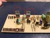
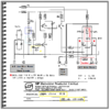
Recently I’ve been having problems with the wire speed on my Ideal 120n Mig welder being far too slow. It is an old machine and there is no parts availability so I can’t just buy a new wire speed control PCB. I have read a few threads on welding forums and watched a few YouTube videos of people repairing similar issues on different machines by replacing the thyristors on the PCB. I would like to try this but I can’t seem to find new ones and I have no way of working out a modern equivalent. This is probably because I have no idea what I am looking at, I’m not even sure that they are thyristors this is just something I have read.
Any help in finding a part no. for a readily available part will be greatly appreciated. I will add a picture so you can see what I am working with.
Thanks
 

Attachments

  • 36F7E5A2-17AE-4A22-BA6B-45D9CB1EF6D5.jpeg
    36F7E5A2-17AE-4A22-BA6B-45D9CB1EF6D5.jpeg
    319.1 KB · Views: 13

Bluejets

Oct 5, 2014
6,927
Joined
Oct 5, 2014
Messages
6,927
Wire feed speed can be affected by a few things.
Dirty or rusty wire.
Outer feeder tube dirty, blocked or bent
Feeder clutch slipping or worn
Feed motor faulty or worn out
I doubt changing the thyristor would change enything but it would be my last thought.
 

Pmax

May 28, 2022
11
Joined
May 28, 2022
Messages
11
Dirty wire or a damaged feeder tube where my first thought so I had a whole new euro torch as my old one was tired and not worth a new liner and some fresh wire in case. I don’t know about the condition of the motor but although it is running slow it is still extremely strong and not making any untoward noises I know this doesn’t mean it’s definitely ok but it’s not giving me cause for concern.
When I turn the dial up on the wire speed I can hear the motor picking up speed but when it gets to setting 4 out of 10 it just stop’s advancing and it does this even when it’s not pushing the wire. Like I said I’m only thinking thyristors as I’ve read that other people have solved similar problems that way I’m clutching at straws really but I’m not sure what to try next.
Thanks
 

Bluejets

Oct 5, 2014
6,927
Joined
Oct 5, 2014
Messages
6,927
Check the pot first then with a multimeter. I'd be inclined to disconnect it from adjoining circuitry first though as you might get inaçcurate results. Mechanical things tend to stuff up before electronics on a "wearout per day" basis.
 

73's de Edd

Aug 21, 2015
3,622
Joined
Aug 21, 2015
Messages
3,622
Sir Pmax . . . . . .

That circuit board certainly suggests it being of '80's lineage.
I am unable to see all of the right side of the board . . .particularly all of the speed pot ?
Also,in need of a GOOD photo of the bottom foil side where the REAL analysis of inner connections could be made.
I also don't want to suspect those 400V / 6 A T400 units as being your faulting.
As for their drive, from what info that I can interpret from only the topside board viewing, I suspect 2 of those 3 discrete transistors , being used in a NPN and PNP transistor configuration into a . . . " Quasi / Psuedo" . . . . unijunction oscillator .
Your large round speed pots resistance affects the osc adjustment drive and feed motor speed.
Look . . . berry-berry cawefuwwy . . . . . la Elmer Fudd . . .at your speed pot, and sitting beside it, to see, what is PROBABLY being an additional trim pot . . . . it looks like an Italiano PIHER brand.
I am expecting that the two would work in series to let the large pot run thru normal speeds . . . . and the small ( factory set) trim pot, establish that speed spread.
What I would be investigating , is to see if some adjustment of the trim pot would extend your max wire feed speed range, back to where it was.

PROCEDURAL . . . .

Take a Mini Sharpie and initially place a hash mark in the white insert across to the peripheral black surround.
This referencing lets you " find your way out of the forest " to return to an ORIGINAL trim pot stetting, if required .

That pot was intended to be adjusted with a special insulative 0.1 in hex adjustment tool, inserted in its central hole.
A workaround is to use a fitting hex wrench . . . . . or if you don't have such, in days past I have: . . . . .
Seeked out a jewelry screwdriver sets standard blade that just crossfits into the hex hole.
Sanded a chopstick end into a fitting hex end.
Use a #11 Exacto knife in its handle and finger support the back of the pot from your opposing pressure, as you insert the blade in the hole and get just enough blade "bite" into the hole such that you can then rotate the surrounding white insert.

NOW . . . . .Test / Adjust and see if that adjustment will find that extra speed.

ACTUAL FAULT . . . .

For that time related change, and its cause, in just viewing parts on the board. I might suspect a higher value resistor having drifted upwards in resistive value.
HOWEVER . . . . this unit is using carbon film units and those units are being quite reliable with time of use onset. One would be more suspect of older genre carbon COMPOSITION MOLDED resistors in experiencing resistance / time shift.
I am seeing a Brown-Grey-Yellow-Gold . . . .180K 5% in center left foreground as the highest value of resistance seen.
ALONG with the factory having need to have installed another 180K "trimming" unit that is humping another resistor of that same value in the right rear area.
Also that Blue E cap might be a critical timing part . . .OR . . .it may just be serving as a mere bypassing function.

We e e e e e e e e e e l l l l l l l l l l . . . . .NOWGOYEFORTHANDDOITTOIT ! .
. . . and inform us of your finds .


ADDENDA . . .
Where you just said . . .

I tested from the centre pin to the left pin and got a nice smooth reading from 0 to just under 1k ohms and then did centre pin to right pin and got the same result
Now try my procedure above . . .


73's de Edd . . . . .


Be sure to enjoy your life fully . . . . . . . . because, just like milk, it also has an expiration date.

.
 
Last edited:

Pmax

May 28, 2022
11
Joined
May 28, 2022
Messages
11
Ok I removed and tested the pot this morning I tested from the centre pin to the left pin and got a nice smooth reading from 0 to just under 1k ohms and then did centre pin to right pin and got the same result but in the opposite direction. I take it this means it’s ok sorry I really know nothing about electronics.
 

Pmax

May 28, 2022
11
Joined
May 28, 2022
Messages
11
Thanks
I will add a pic of the back side also a screen shot of a diagram I believe (but not 100% sure)to be of the board in question that I found on line. The thing with the trim pot I tried before I took it all apart and it only made a very small difference to the speed.Screenshot_20220529-102635_WhatsApp[1].jpg Screenshot_20220529-102647_WhatsApp[1].jpg
 

Pmax

May 28, 2022
11
Joined
May 28, 2022
Messages
11
Also I just re attached the pot and tested it while adjusting the trim pot it made no difference to the reading what so ever. So I tested the trim pot and it went smoothly from 0-500 ohms
 

PETERDECO

Dec 19, 2019
239
Joined
Dec 19, 2019
Messages
239
I see a couple of connections on the bottom of the PC board that look kind of "iffy." They're on the upper 1/3rd section.
 

Pmax

May 28, 2022
11
Joined
May 28, 2022
Messages
11
Thanks
I just reflowed all the joints on the back of the board unfortunately this didn’t seem to make any difference
 

73's de Edd

Aug 21, 2015
3,622
Joined
Aug 21, 2015
Messages
3,622
Sir Pmax . . . . .

OH TAY ! . . . . .that schematic is being your MONEY SHOT !
Let me delve into any enhanced definition and more info to be extracted . . . .

INITIALLY . . . .
There is confirmation of my ascession of the SCR type along two other usable substitutes.
The oscillator / pulse generator / Schmitt trigger / SCR driver . . . .aspects, being just as I had surmised
The most suspect component of those seen would be the development of internal leakage / or / and/ capacitance decline of that BLUE electrolytic cap.

Let me snoop out more of that indistinct / blurred schematics circuitry.

73's de Edd . . . . .

I bought a self-learning record to learn Spanish. I turned it on one night and went to sleep; the record got stuck. . . . . now I can only st-st-st-stutter in Spanish.


.


Last edited:

73's de Edd

Aug 21, 2015
3,622
Joined
Aug 21, 2015
Messages
3,622
Sir Pmax . . . . .

NOW IN REFERENCING TO . . .


upload_2022-5-29_9-45-20.png
I am seeing HIGH agreement between that welding forums schematic and your board, with only yours, having used 4 discrete diodes in top left corner whereas his was using RD2-WL02 a potted rectifier block and using different parts positionings at other parts of the board..
Also as clear as the duped schematic came out, I see and seriously question that value of 18 ohm resistor in the + feed line to your feed motor . . . . . . I think that a frontal decimal point dropped out.
Look at his board and see the use of a 0.22 ohm 5 watt wire wound resistor . . . which would be in close agreement of the use of a 0.18 ohm unit on yours.
.
https://www.mig-welding.co.uk/forum/attachments/dsc00018-jpg.3681/

Comparing that schematic to your board I actually see nothing between the two SCR's and the frontal connector pins block.
But there is being one bare jumper wire on yours . . . if having a production change.

The two shades of BLUE squares are being your series arranged speed pot and trimmer adjust.

My initial bad part suspicion is being that 10 ufd @ 40 VDC Blue Electrolytic capacitor , due to its . . . .? leakage or ? capacitance decline.
That 1950's thru 1980's 40 VDC cap voltage rating is now being a 2022's . . . 50 or 63 VDC rating.

FACTOIDS . . . . .

The combinational effect of steering diodes DP1 and DP2 in series conjunction with SCR1 and SCR2 is giving you a sequential and alternate continuous steam of positive power nodes to power your DC feed motor.
If one of the SCR's failed to trigger and conduct you would then hear the COARSE running sound of that DC motor . . . (akin to an 8 cylinder car running on only half of its cylinders.)
Surely you are not hearing that from your feed motor .

IF a required a work around was to be considered, one would measure the DC voltage present on that motor at min and max wire feed speeds.
With OUR interest being of the present max feed motor speed.
Then you test out the unit by clipping in an electrolytic capacitor across the polarity observed + and - motor leads.
The capacitors voltage rating will be selected so as to be of a safe overvoltage rating of that max motor speed voltage .
E.G. . . . . . on a voltage read of . . . 25 . . . . . use a minimal 50 / 63 volt rating.
And start with a capacitance test of 470 ufd and if the speed is still being deficient . . . step up to 1000 ------1500---------2200 ufds.
You are now just making more efficient harvesting + storage of that developed voltage, such as is NORMALLY being done on typical linear based power supplys.

Standing by . . . . . .leisurely . . . . .
EatingPopcorn.jpg


73's de Edd . . . . .

Teamwork is a blessing in disguise; since it is also routinely allowing you to blame someone else.

.
 

Attachments

  • upload_2022-5-29_8-46-55.png
    upload_2022-5-29_8-46-55.png
    69.3 KB · Views: 5
Last edited:

Pmax

May 28, 2022
11
Joined
May 28, 2022
Messages
11
Ok I will try and get a new (10uf 63v) capacitor tomorrow and see how I get on. I’m assuming that the work around stuff is for if this doesn’t work or have I got the wrong end of the stick.

Thanks for your reply’s I really appreciate the help
 

Pmax

May 28, 2022
11
Joined
May 28, 2022
Messages
11
Ok so I finally managed to get and change the capacitor and unfortunately it hasn’t improved the problem but while playing around with it today, I discovered that the voltage to the wire feed motor changes quite drastically under load. For instance with the welder on power setting one, the voltage output to the motor is 10v—44v with the motor disconnected. But with it connected it’s only 7v-17v. This happens on all 6 power settings with the voltages ending on power setting 6 at 14v-81v disconnected and 8v-35v connected.
I don’t know if this information helps or may be points to a different potential cause for my lack of wire speed?
 

73's de Edd

Aug 21, 2015
3,622
Joined
Aug 21, 2015
Messages
3,622
Sir Pmax . . . . .
I was just looking at the inherent circuit design, and with it mostly being resistors . . .inherently stable and reliable components . . and that one E-cap.
With it being in a time constant circuit and any decline, inherently decreasing the on time drive to the SCR's .
Less on time means less power output.
Now we know, it was still up to its job.
Now, about your two voltages to the motor . . . unloaded and loaded . . . they are as is to be expected.
With PRIME consideration, to be reserved to the loaded condition.
Looking at that schematic just above my GREY marked in " Wire Feed Motor" and the two motor polarities they have drawn in a series of POSITIVE voltage nodes that your DC motor is fed by.
Look at my drawing below and see that at the top left corner depiction, that I have redrawn that . . . in living color . . . for the POSITIVE SINE POWER NODES.
That represents full power to the DC motor, and the two drawings below show the mid and low power pot settings where the SCR's clip and shorten the power duration's of the sines.
VIEW the cumulative amounts of RED portion as your motor power available.

MOVE to the right half's 3 drawings and consider this representing the utilization of a DC storage capacitor . . .Electrolytic . . . in averaging out and storing that voltage, as a purer DC voltage .
At right bottom see the constant level of DC now averaged out and being constantly available and the additional amount contributed from the + nodes.
Note the increase in the center drawing if the capacitance was increased.
Yet again, the top drawings increase, if the capacitance was increased even more.
This depiction of the + nodes was merely for the contribution of each of them to the available DC steady state power.
A more true to life situation would be akin to 5 foot waves on the ocean surface as far as the eye could see. . . . and the level of the ocean.
Should all of the waves stop, they would all settle down and cause rise of the prior ocean level.
These + nodes are averaging out and bringing the DC level up to as high as a max of 70.7 % of their amplitude. ( Dependent upon power consumption and added capacitance . )

upload_2022-6-2_8-5-53.png


APPLICATION . . .
As mentioned , initially evaluate the FEED MOTOR supply voltage at max speed and then shunt that supply with a 470V @ 50 /or / 63V E-cap
Since 35V was the highest supply voltage being read with motor CONNECTED.
Read the new developed voltage with E-cap in circuit . . . . . if still being deficient in speed improvement, gradually up the capacitance.

73's de Edd . . . . .


Bare feet magnetize sharp metal objects so they always point upward from the floor.
 

Pmax

May 28, 2022
11
Joined
May 28, 2022
Messages
11
Ok I’ve just got my capacitors and I’ve tried to fit the first one a 470uf 63v I connected it in parallel with the motor feed and it blew a small glass fuse (4a) on the front panel of the welder. So I’ve stopped to check if or what I’m doing wrong
Thanks P max
 

73's de Edd

Aug 21, 2015
3,622
Joined
Aug 21, 2015
Messages
3,622
Are you certain of installed polarity, as comparing it to the meter leads of test meter ? Also you should see an increase of voltage being read after install.
 

Pmax

May 28, 2022
11
Joined
May 28, 2022
Messages
11
I did check the polarity before I started but that doesn’t mean I didn’t make a mistake. I stopped as soon as the fuse blew thinking I had better check that I had properly understood what I was supposed to be doing. Now I know I was doing the right thing I will try again tomorrow.
 

73's de Edd

Aug 21, 2015
3,622
Joined
Aug 21, 2015
Messages
3,622
This time around, have the meter clipped into circuit and be getting a reading.Have the cap installed with the negative lead connected, but with the + lead disconnected and free. Then move the cap positive lead to connect, but for just an instant. If no fuse blowing fallacy again, then connect cap + lead and observe available voltage and motor speed affectation.
 

Pmax

May 28, 2022
11
Joined
May 28, 2022
Messages
11
Ok so I’ve been and tried again. I didn’t do what you suggested in your last post, because I hadn’t read it yet. I put in a fresh fuse and it worked first time - with the 470uf cap, the voltage picked up 15v or so which improved the speed, but still left room for improvement. So I changed it for a 1000uf cap and that has given me almost the full range of speed back. So problem solved I think.
Thanks again for all your help I would have been weighing it in and buying a new machine without it!
 
Top