73's de Edd
- Aug 21, 2015
- 3,622
- Joined
- Aug 21, 2015
- Messages
- 3,622
YOU SAY . . .
it will probably take close to a month to arrive
I have no idea of your location . . . . .¿ ¿ ¿ ¿ are we located in some obscure and remote 1869th World country ? ? ? ?
Do you not have knowledge of any/ some LOCAL person who is an electronics hobbyist and has some related "stuff" / parts .
Or an electronics repair shop or some local college that instructs in electronics and one of their instructors or even a student of same .
An amateur radio ( HAM) hobbyist and their on hand parts resources.
A high school "GEEK" who is, all time, tearing down curb find electronics for their "free" parts resourcing and using them.
I believe that if they are confronted and you explained your situation , that any of these would be equally interested and even GIVE you the required 5 cent 1 K resistor and very short length of 20-26 gauge insulated wire . . . . . or . . . . . its even for free from one of the wires in a multiple cable used by phone installers . . . . or common CAT-5 cable will yield its multiple usable wires.
Isn't a small simple / common on off switch locally available at a big box Home Depot or Lowe's or your equivalent local hardware store ?
Assuredly . . . . . a sympathetic person with their peaked interest of the final results, would also do your minor soldering ***** work.
***** That soldering iron you referred to . . . . . is a VERY good buy . . . . and my #1 son has one like it and uses it, and it works fine for him.
73's de Edd . . . . .
Last edited:

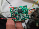

") also i wanted to check the tweeter for you but it was too late, i cut some wires already, going to think what to do next, thanks anyway!!
also i wanted to check the tweeter for you but it was too late, i cut some wires already, going to think what to do next, thanks anyway!!