Maker Pro
Maker Pro

Multiplex IC 5 inputs and 5 outputs custom?

StealthRT

Sep 4, 2010
146
Joined
Sep 4, 2010
Messages
146
Hey all I am wanting to know if there is an IC that allows me to do the following:


    • - Have 5 inputs
    • - Have 5 outputs
    • - Ability to take any input # and direct it to any output #
The latter bullet there is the main goal.
tfIZS.png

So in the image example above say that I needed the following examples:

Input 1 output to output 4.
Input 3 output to Output 1.
Input 3 output to Output 3.
Input 4 output to Output 1.
Input 1 output to Output 1.
Input 2 output to Output 5.

...and so on....

What I would be hooking up to the input would be either Ground, 5V or 3.3V which would need to output the same as its input.

Note that I plan on using an Arduino so if the IC requires interaction from the Arduino in order to switch the outputs then I will have the means to do so.

Is there any IC that would allow me to do the above?
 

kellys_eye

Jun 25, 2010
6,514
Joined
Jun 25, 2010
Messages
6,514
What you're describing is a "cross-point switch" - digital and analog versions are available but probably in sizes larger than you actually want i.e. 8x8.

It would be possible to build one using discreet gates or even a FPGA but since this method of switching has been around for 'ages' you may as well go for standard devices.
 

StealthRT

Sep 4, 2010
146
Joined
Sep 4, 2010
Messages
146
I will need to be able to use all of the inputs and outputs at the same time.

Example:
Input 1 --> Output 4 (5v)
Input 2 --> Output 1 (RX)
Input 3 --> Output 5 (TX)
Input 4 --> Output 2 (3.3v)
Input 5 --> Output 3 (gnd)
 

@xi@g@me

Dec 15, 2016
86
Joined
Dec 15, 2016
Messages
86
You may want to use several 4051 ICs (analog multiplexers), each of them having all your inputs, and one of the outputs. If you want, say, input 4 to ouput 2, set the multiplexer that has it's output to wire 2 to use input address 4. And so on.
 

StealthRT

Sep 4, 2010
146
Joined
Sep 4, 2010
Messages
146
Would the Crosspoint switch work even if its Analog for the RX/TX? The RX/TX/5v/3.3v/grd will be coming into the IC via a FTDI ft232r chip. Also most of these I've seen are either for Audio/Video or LVDS signals?
 

kellys_eye

Jun 25, 2010
6,514
Joined
Jun 25, 2010
Messages
6,514
If it's an analog switch it will accept 'any' input between the limits defined by the datasheet - if you allocate a logic level for TX/RX or simply 'pass through' (what you put in, you get out - possibly with a very small % loss) a DC voltage (where 0V is 'ground') then you have every signal state you could need.

What you do after the signal has passed through the x-point switch is entirely your decision.

Look into how any basic analog switch (like the CMOS 4066) works and you can see how the same principle is applied in a x-point device.
 

StealthRT

Sep 4, 2010
146
Joined
Sep 4, 2010
Messages
146
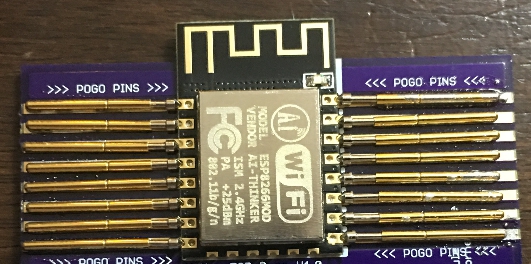
What I am looking to accomplish is taking this layout:
iekAB.jpg


and connecting those pogo pins to the multiplex/demultiplexer/crossbar switch/cross point switch in order to allow for different pcb models that have different pin layouts in order to flash firmware to them using the FTDI.

Hopefully knowing that allows you to understand the overall design of what I am trying to do.
 

JWHassler

Dec 22, 2014
86
Joined
Dec 22, 2014
Messages
86
Still a little hazy on what you are doing: in the picture of the pogo-pin fixture I see a setup that only has ONE possible connection scheme.
Are you pre-programming ESP8266's and then placing them on various PCBs?
 

StealthRT

Sep 4, 2010
146
Joined
Sep 4, 2010
Messages
146
Still a little hazy on what you are doing: in the picture of the pogo-pin fixture I see a setup that only has ONE possible connection scheme.
Are you pre-programming ESP8266's and then placing them on various PCBs?
Yes sir.
 

kellys_eye

Jun 25, 2010
6,514
Joined
Jun 25, 2010
Messages
6,514
How many actual different combinations of connection will there be?
 

kellys_eye

Jun 25, 2010
6,514
Joined
Jun 25, 2010
Messages
6,514
Make a list of the pins that have an actual 'change of state' and a list of the signals that will be used on them. It may well be simpler to design a discrete component (gates, transistors etc) circuit to do the 'switching'.

It doesn't sound much different to the way this used to be done for universal EPROM programmers.
 
Top