Maker Pro
Maker Pro

Mysterious diode identification help!

wdoug72

Jul 28, 2012
21
Joined
Jul 28, 2012
Messages
21
Kris, it seems that your schematic has two T1 elements on it. I'm assuming you want more info on the element labeled T2 in the image. So I removed T2 and attached a picture of which pins have continuity. As for the resistance values I'm not exactly sure. I set my multimeter to 200ohm setting and it seems to briefly flash numbers at random between the pairs of pins then drops down to zero.
 

Attachments

  • oscilator.jpg
    oscilator.jpg
    145.6 KB · Views: 306

wdoug72

Jul 28, 2012
21
Joined
Jul 28, 2012
Messages
21
I also will be ordering 4 new 2N6547 transistors from Mouser today.
Edit: Is there anything else I should order with the transistors? Parts I should replace?
 
Last edited:

KrisBlueNZ

Sadly passed away in 2015
Nov 28, 2011
8,393
Joined
Nov 28, 2011
Messages
8,393
Yes, you're right, it's T2. Thanks for that information; I will correct and update the schematic.

Re parts to order along with the transistors. I suspected those big carbon resistors because they can be a common fault, but they're OK at the moment, so it's up to you whether you replace them or not. I don't know their power rating; maybe 5W. Best replacements would be metal film resistors.
 

KrisBlueNZ

Sadly passed away in 2015
Nov 28, 2011
8,393
Joined
Nov 28, 2011
Messages
8,393
Updated schematic.

attachment.php
 

Attachments

  • Wdoug72.002.gif
    Wdoug72.002.gif
    14.7 KB · Views: 1,689

wdoug72

Jul 28, 2012
21
Joined
Jul 28, 2012
Messages
21
Update:
Sorry for the delay have had quite a busy holiday. So replaced the transistors today and decided to fire up the machine and see what happens. To my dismay the machine did work for a second but T1 got hot and began to burn! The fuse ended up burning out but the damage was done. Now I'm unsure of what to do as the specs for this circuit elementary unknown. Thoughts?
 

KrisBlueNZ

Sadly passed away in 2015
Nov 28, 2011
8,393
Joined
Nov 28, 2011
Messages
8,393
T1 burnt up? That's the component in the bottom right corner next to where the mains comes in?

If so, it was probably faulty. There's not much that can go wrong with a common-mode choke that will make it burn up, apart from some kind of breakdown between the two windings.

Its function is just interference suppression, so you could remove it, and temporarily link across its windings. The circuit should work without it, but it will probably inject a lot of interference into the mains.

You should be able to replace T1 with a common-mode choke from a defunct appliance with a similar power rating, if you have one.
 

wdoug72

Jul 28, 2012
21
Joined
Jul 28, 2012
Messages
21
Would a choke out of a computer power supply work? Have a couple of these hanging around.
 

davenn

Moderator
Sep 5, 2009
14,260
Joined
Sep 5, 2009
Messages
14,260
what sort of choke ?

show a pic,
I suspect you are referring to the large coil ones in the DC output lines ?
if so, no they would be suitable

Dace
 
Last edited:

KrisBlueNZ

Sadly passed away in 2015
Nov 28, 2011
8,393
Joined
Nov 28, 2011
Messages
8,393
As long as it's from the mains input path, and it has four connections and two windings, it should be suitable.
 

davenn

Moderator
Sep 5, 2009
14,260
Joined
Sep 5, 2009
Messages
14,260
As long as it's from the mains input path, and it has four connections and two windings, it should be suitable.

agreed,
I just had visions of him referring to one of those large toroid ones in the output ;)


D
 
Last edited:

wdoug72

Jul 28, 2012
21
Joined
Jul 28, 2012
Messages
21
Took one off a 230 watt power supply on the mains side of the circuit (picture of old and new choke). I soldered her in and am wondering is there anything I should check before firing it up?
 

Attachments

  • image.jpg
    image.jpg
    157.1 KB · Views: 296

KrisBlueNZ

Sadly passed away in 2015
Nov 28, 2011
8,393
Joined
Nov 28, 2011
Messages
8,393
Just make sure it's rotated correctly. Measure resistance across the mains input pins; you should measure open circuit. If you measure short circuit, you need to rotate the choke 90 degrees.

Good luck!
 

wdoug72

Jul 28, 2012
21
Joined
Jul 28, 2012
Messages
21
So I tested the continuity of the choke and installed it on the board. Powered on the board and instantly the fuse blew. I then unplugged the transducers and plugged in the machine. The buzz of the transistors could be heard BEFORE I even turned on the machine! Flipping the switch did nothing. Unplugging the
machine or popping out the fuse were the only things that turned it off. Thoughts?
 

KrisBlueNZ

Sadly passed away in 2015
Nov 28, 2011
8,393
Joined
Nov 28, 2011
Messages
8,393
Sounds like the mains switch has failed short. There's no way that you should be able to hear a buzzing from the board if the mains supply to it is switched off.

The board will not oscillate with the transducer disconnected. If you run it in this state, the transistors may get hot; I'm not sure.

There may be another fault on the board. Possibly a short across the DC rail. Could be C1, C2, C3 or C4, or maybe C5 or C6. Check the diodes in the bridge; if there's been an overcurrent, they may have failed. Then check resistance across C4. It should read open circuit if you're using a digital multimeter.
 

davenn

Moderator
Sep 5, 2009
14,260
Joined
Sep 5, 2009
Messages
14,260
as Kris said, there has to be other faults.

that inductor didnt cook without reason. its inferring that there's a short or near short on the hi voltage side of the main switching transformer...

1) a shorted winding in that transformer
2) bridge rectifier shorted
3) switching transistor (s) shorted

are some of the choices

Dave
 

wdoug72

Jul 28, 2012
21
Joined
Jul 28, 2012
Messages
21
Worked the mains switch back and forth and now
it's working. The smaller diodes checked out fine. Also found one of the metal circuit lines on the pcb was broken off so I fixed that and now when the board is switched on it blows a fuse instead of running. The missing circuit line connected the neutral side of c3 to d1. Now I'm going to
check the capacitors mentioned. Thanks everyone for the help so far.
 
Last edited:

wdoug72

Jul 28, 2012
21
Joined
Jul 28, 2012
Messages
21
Most of the information I'm reading online says I need a capacitor tester to really diagnose capacitor problems. When I set my multimeter to contiuity test all the capacitors show an open circuit (c1-c6)
 

KrisBlueNZ

Sadly passed away in 2015
Nov 28, 2011
8,393
Joined
Nov 28, 2011
Messages
8,393
OK that's good. I thought maybe one of the capacitors was shorted.

You can't check their values without a capacitance meter. It's also possible that a capacitor is breaking down when the voltage across it reaches a certain point, but I would expect some visible or audible sign from the capacitor if that was happening.

With the circuit simply blowing fuses it's impossible to apply any kind of structured diagnosis to it. You need to isolate parts of the circuit. There are only two parts to that circuit: the power input circuitry and the oscillator. You can disconnect the oscillator by unscrewing and removing all four screws on Q1 and Q2.

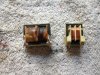
This brings up another point. Is it possible the insulation between the transistors and their heatsinks has failed in some way? Did you inspect the insulating washers between the transistors and the heatsink? These can sometimes develop thin cracks that can cause insulation breakdown. Also, are the screws properly centred in the holes and insulated from the heatsink metal? This is usually done by plastic inserts that keep the screw perfectly centred in the hole. If these aren't present, or are damaged, the screw could touch on the metal of the heatsink and cause this problem. The problem will only show up if the heatsink is screwed to something that's earthed, like the chassis. If you're running the board by itself, not mounted to the chassis, a problem with insulation to the heatsink will not show up, but it will show up later when you refit the board.

I suggest you unscrew and remove all four screws on the Q1/Q2 heatsink, replace the bridge rectifier diodes again (since they may have been damaged), and power up the board again. I expect it won't blow a fuse, but if it does, the only components that can be faulty are C1~C6, unless there's a short circuit somewhere that's not part of the circuit diagram.

Edit: I would also replace the mains switch, when you've fixed the underlying problem. It has obviously been damaged by all the heavy current flow when the fuse blows, and it will not be reliable. It could even be a fire hazard.
 
Last edited:

wdoug72

Jul 28, 2012
21
Joined
Jul 28, 2012
Messages
21
Update:
Replaced the bridge rectifier diodes again and removed the screws from Q1 and Q2. I then attached it to the chassis and powered it on. The fuse did not blow. When I replaced the transistors I inspected those insulators for the transistors and they seemed fine. The transistors sit on insulating gaskets when attached to the heat sink and I replaced those as they were cracked.
 
Top