Maker Pro
Maker Pro

Nakamichi RX-505 Low 12V + and - Rails

KilgoreCemetery

Apr 12, 2017
258
Joined
Apr 12, 2017
Messages
258
I've been working on a Nakamichi RX-505 cassette deck. Long story short, the door wouldn't open or close on its own like it's supposed to, and I've found that the regulated + and - 12v rails only measure about +3v and -3v. If I disconnect all the wires that are supposed to supply +12 to the rest of the unit, it goes up to about 10v, but no matter what wire I connect first, the voltage immediately drops to some degree or another (8v, 6v, 3v, etc).

Maybe I'm just misunderstanding what the circuit is for, but isn't it supposed to hold it at 12v?

The + and - 20v supply to the regulator circuit never changes. I've tested capacitors, replaced transistors, checked diodes, and recently swapped out the dual opamp. Nothing has made any difference so far.

Sorry for the rough-looking schematic. The original scan was blurry and compact, but it's all I have to work with.

Any help would be greatly appreciated
 

Attachments

  • Nakamichi Regulator Schematic.jpg
    Nakamichi Regulator Schematic.jpg
    208.6 KB · Views: 8

Harald Kapp

Moderator
Moderator
Nov 17, 2011
13,724
Joined
Nov 17, 2011
Messages
13,724
My primary suspects would be the main filter capacitors (1) and the rectifier (2):
upload_2019-6-22_19-18-42.png
How do you measure the voltages? Do you have access to an oscilloscope? The 3 V seen by a multimeter may be the result of heavy AC content on top of the DC. Lacking an oscilloscope you may try to measure AC content using your multimeter in AC setting - possibly decoupled by a 1µF capacitor to block DC content.
Measure AC at the input of the rectifier, does it follow your observations or is it stable when the load current is changing?
The rectifier itself may have a defect diode within, that would couple lots of AC onto the supposed DC output.
 

(*steve*)

¡sǝpodᴉʇuɐ ǝɥʇ ɹɐǝɥd
Moderator
Jan 21, 2010
25,510
Joined
Jan 21, 2010
Messages
25,510
This schematic has large parts of it going right to left, so it's a bit odd...

A key thing you show is the voltage either side of Q402. It shows that there is ample unregulated voltage ( 19.7V) upstream of it. That means everything to the right of it is likely OK (with a caveat mentioned below).

Q403 turns Q402 on. Q404 turns Q403 off enough to reduce the output voltage to that set by IC401, the zener diode and the resistors around it.

Given the voltages around Q404, this is turned completely off. The voltage at the base of Q403 is very low, as if Q404 was turned on quite hard. There are several possible problems, most likely I think is that C403 has failed short circuit, and the voltage on the base of Q403 is due tot he forward voltage of D408. An alternative is a near E-C short on Q404 that just happens to cause a voltage drop of 700ish mV.

If C403 is a tantalum, then this is a typical failure mode, and I'd replace it. It does appear to be a value that is less likely to be a tantalum, and if that is the case other capacitors may be suffering from the aging effect that claimed this one. Here is the caveat from above -- it is possible that the filter capacitors (you have circled them and labelled them "1" may also need replacement.

I can't see enough of the negative rail to be sure, but since the op amps are powered from the regulated supply, the fault may be entirely in the positive supply. This is somewhat backed up by the -5V on the collector of Q408 (a symmetric fault would see this as -700ish mV).

Try replacing C403 and lets see where that gets us.
 

KilgoreCemetery

Apr 12, 2017
258
Joined
Apr 12, 2017
Messages
258
My primary suspects would be the main filter capacitors (1) and the rectifier (2):
View attachment 45555
How do you measure the voltages? Do you have access to an oscilloscope? The 3 V seen by a multimeter may be the result of heavy AC content on top of the DC. Lacking an oscilloscope you may try to measure AC content using your multimeter in AC setting - possibly decoupled by a 1µF capacitor to block DC content.
Measure AC at the input of the rectifier, does it follow your observations or is it stable when the load current is changing?
The rectifier itself may have a defect diode within, that would couple lots of AC onto the supposed DC output.

I typically measure voltages with my DMM with the black probe to chassis ground for DC. I do have a Tektronix 335 scope and while it does help me quite a bit, it's not great at providing detailed voltage measurements.

I've successfully used my DMM to find faulty capacitors before by testing for AC across the leads of capacitors, but was not able to find any using this method with this unit. If I probe the rectifier outputs, the VDC doesn't fluctuate and it doesn't change with load either. It's always + and - 20v. Checking for AC across the outputs just gives me a rotating list of numbers, which is what I normally see when there's no AC.


This schematic has large parts of it going right to left, so it's a bit odd...

A key thing you show is the voltage either side of Q402. It shows that there is ample unregulated voltage ( 19.7V) upstream of it. That means everything to the right of it is likely OK (with a caveat mentioned below).

Q403 turns Q402 on. Q404 turns Q403 off enough to reduce the output voltage to that set by IC401, the zener diode and the resistors around it.

Given the voltages around Q404, this is turned completely off. The voltage at the base of Q403 is very low, as if Q404 was turned on quite hard. There are several possible problems, most likely I think is that C403 has failed short circuit, and the voltage on the base of Q403 is due tot he forward voltage of D408. An alternative is a near E-C short on Q404 that just happens to cause a voltage drop of 700ish mV.

If C403 is a tantalum, then this is a typical failure mode, and I'd replace it. It does appear to be a value that is less likely to be a tantalum, and if that is the case other capacitors may be suffering from the aging effect that claimed this one. Here is the caveat from above -- it is possible that the filter capacitors (you have circled them and labelled them "1" may also need replacement.

I can't see enough of the negative rail to be sure, but since the op amps are powered from the regulated supply, the fault may be entirely in the positive supply. This is somewhat backed up by the -5V on the collector of Q408 (a symmetric fault would see this as -700ish mV).

Try replacing C403 and lets see where that gets us.
I've replaced C403, but no change. I have an ESR Blue meter and went ahead and checked all of the electrolytics in the + and - 12v regulator section. Everything from C401 to C409. They are all well within tolerance. I've also checked for AC across their leads since I'm still getting used to the ESR meter.

I previously replaced Q404 thinking the same thing, but I still got a significant voltage drop under load. I went ahead and pulled it and tested it out of circuit just in case something is causing it to fail, but it tests fine. I put the original transistor back in, but no change.

I really don't understand where that negative voltage is coming from in the positive section. It's higher on the left side of R404, which makes me think that it has to be coming from that side, but the only way to link that with the negative supply would have to be through the dual opamp, which I've swapped out.

I do get a very small amount of AC (about 2mV) if I probe pins 2&3, but it's the same on pins 5&6 for the negative side. I feel like that's more of a voltage fluctuation than actual AC though. If I probe across the supply side of the opamp, I get no AC whatsoever.
 

KilgoreCemetery

Apr 12, 2017
258
Joined
Apr 12, 2017
Messages
258
So.. I went ahead and used my scope to see what the output of the rectifier actually looks like and I did find that the positive side has less amplitude than the negative side. Would this indicate a problem within the rectifier?
 

KilgoreCemetery

Apr 12, 2017
258
Joined
Apr 12, 2017
Messages
258
The rectifier on the 5v regulated supply side is the same part number. I pulled them both and tested out of circuit. They tested the same. I swapped them when reinstalling and there's still no change to either regulated supply. The 5v side always measures 5v with a maximum deviation of about 0.01 volts.
 

73's de Edd

Aug 21, 2015
3,622
Joined
Aug 21, 2015
Messages
3,622
Sir Kilgore Cemetery . . . . .

Where ? you go o o o o o o o o ?
(Had a backlog on enbalming jobs and not caught up yet ?)


Submitted, herewith, an evaluation of your situation . . . .

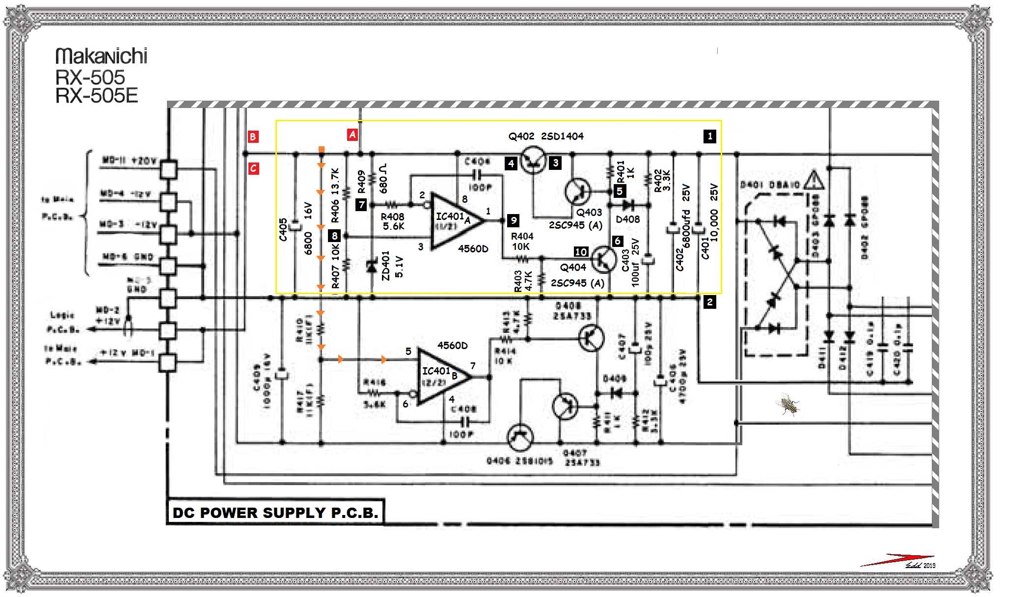
I see the initial +20volts (19.7 in your situation) is coming into BLACK 1 and with BLACK 2 being the common ground for both + and -supplies.
Initially that 10 . . . .TOUSAND motherfarads of capacitance DOES check out against the parts list . . . along with an additional 6800 shunting it.
Now thats enough capacitance for a 12V @ 15 amp supply to be outputted !
OR . . . . for a low level audio amp supply to have a background noise threshold lower limit, of a mouse peeing on a cotton ball !
Now, as far as the negative supply, all seems to be well with it, since it is being in error as an equally like amount as the positive supply counterpart is.
It is just a duplicate build of the + power section . . . built upside down, backwards and reverse polarity, with the one minor difference of the ORANGE ARROW path supplying it a sample of the positive supply to be able to track.

Seems like if there is not a problen brought on by overloading of the positive supply, that the fault should be within the YELLOW BOX area.
First . . . . in a no power up yet, situation . . . . . ohm out the soon to be +12V output bus at any of the RED A-B-C references. See if there is any chance of there being a 12ohm or less reading, that woulld be loading and pulling down that 12V supply.
RED A feeds up to be switched by , Q412, located directly above IC401 A section, with very low drain to be expected by a logic circuit that it feeds.
RED B and C were not fully tracked down but C branches out a bit lower left down on the schema.
If that clears as not being a fault we can now power up and do some dynamic evaluations.
Phase 1 . . . .
Peparation is to heat the collector lead of Q404 such that it can be tilted and permit its lead be pulled thru its pcb hole and then be floating out of circuit.
Now with your past dealings, I believe that you will be having stocked a 12V zener of 750mw / 1 / or / 2 watt rating on hand or be cannibalizable from other equipment.
If not, a 10.1 or 9.1 value will also fulfill.. We will just get a lower voltage, less the pass transistors voltage drop.

With Q404 no longer influencing the circuitry, along with that added zener we should come up with the most basic regulator circuitry, if you install the zener cathode to the BLACK 5 junction and its anode to the BLACK 2 common ground buss..
IF . . . and heavy on the IF, you did not have the zener, use a 1K resistor instead, and it, plus the R401 combo will make a voltage divider and end up with
~1/2 of your 20 V supply at the emitter of Q402 pass transistor instead of the normal +12V.
If that then creates the expected voltage output , that dispells any overloading pull down of the supply, and we need to examine Q404 in depth.
Power down and reinstall Q404 collector in its hole.
Now power up and we will see if Q404 was what was influencing the low voltage situation.
If the outputted voltage was less than before, short the base of Q404 (BLACK 10 ) or their shared common junction of R403-404 to BLACK 2 . . . . . to the common ground buss . . .BLACK 2.
That should then have Q404 totally free and incapable of influencing the BLACK 5 voltage and the power supplys overall output when Q404 base is grounded out.
If that is not the case , replace Q404 and we continue.

I now await for your testing . . . . ..

FLASH . . . . I see that you just came on with your reply, just as I was finishing this.

The loading down, to pull down the supply still pertains, so confirm that.
SO . . . . with a new Q404 in circuit you can proceed directly to installing the zener or which other option you choose for it and try the shorting of the Q404
to ground and see if the Q404 is not causing a drop of the voltage . ( Not expected now, but an excess base drive level to it instead . )
If it is not, then pull out a 4.7K, 2.2K, 1K and 470 ohm resistors and move to R403 and start sequentially shunting the highest to lowest values of resistors across it.

Each lower value should result in an increasingly higher voltage output from the supply.

Considering so, how close did the lowest value resistor make the supply come up to ?

Next check the R407, R406, R409, R408 . . . . . . . and the R404-R403 resistors for accuracy to value specs. Also is the ZD401 at 5.1 ?

ENHANCED SCHEMATIC REFERENCING . . . . .


Nakamichi-Power-Supply.png

https://i.postimg.cc/7qsGpw5q/Nakamichi-Power-Supply.png


73's de Edd . . . . .


Education is what you have , if you don't have access to books, your Smart Phone or your computer.
 
Last edited:

KilgoreCemetery

Apr 12, 2017
258
Joined
Apr 12, 2017
Messages
258
This one has been a really slow burn, but I finally made some decent progress! I bought a nice 12v power supply and tested all of the motors. They work! Then, I decided to just start rebuilding the power supply. I had already replaced some of the caps and the two C945 transistors, so I pulled Q402 and put it in my little component tester to verify pinout. It showed as back to back resistors. *Facepalm* I don't know how I missed it, but that makes total sense. It's letting voltage by, but can't handle the current flow when you hook up the other boards. I noticed it also quietly killed the two C945's as well.

I swapped in an MJE15032 for the 2SD1404 and replaced the C945's with KSC945's. I don't know if the MJE is a great replacement, but it's what I would normally use for 12v protection relay power supplies and it has higher voltage and current ratings than the 2SD1404. I powered it up using a dim bulb for current limiting and it started to work. After fiddling with some of the mechanical parts, I was able to get it to cycle properly. Huzzah!

Only downside is that it seems to get confused when I take it off of the dim bulb. The +12v supply sits at 15.9v when idle without the dim bulb. With it, it's 14.3v. I'm wondering if the higher voltage is affecting it adversely. Two things stand out. Maybe the MJE15032 isn't a good replacement for the 2SD1404, or maybe the 4.3v zener that I subbed for the 5.1v ZD401 is setting output voltage higher. Can anyone confirm whether those would be causing problems?
 

kellys_eye

Jun 25, 2010
6,514
Joined
Jun 25, 2010
Messages
6,514
errr... 4.3 divided by 5.1 = 0.843 which, when you divide into 12V = 14.23V.........

Clearly the 4.3V zener is the cause.......
 

KilgoreCemetery

Apr 12, 2017
258
Joined
Apr 12, 2017
Messages
258
errr... 4.3 divided by 5.1 = 0.843 which, when you divide into 12V = 14.23V.........

Clearly the 4.3V zener is the cause.......

Thanks! I had a suspicion, but that's exactly the sort of confirmation I was looking for!
 
Top