Maker Pro
Maker Pro

Need help to fix motion detector alarm

mikey5791

Jun 7, 2013
174
Joined
Jun 7, 2013
Messages
174
Dear all,

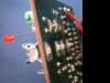
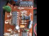
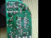
I bought this Motion detector alarm some years ago from a shop vendor initially for
home or car use but recently tested faulty, no power led light or "sensor" not working.
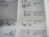
Anyone got any idea how the "sensor" works?

There is no model No. and no schematic can be traced.
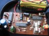
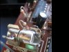
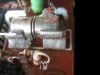
I have attached some snapshot of the item and hope for someone to assist to fix.
Greatly appreciate for any help.
 

Attachments

  • IMG_0045-alarm.JPG
    IMG_0045-alarm.JPG
    32.6 KB · Views: 139
  • IMG_0046-alarmfrt.JPG
    IMG_0046-alarmfrt.JPG
    43 KB · Views: 129
  • IMG_0047-alarmback.JPG
    IMG_0047-alarmback.JPG
    46.1 KB · Views: 137
  • IMG_0048-alarm.JPG
    IMG_0048-alarm.JPG
    39.5 KB · Views: 133
  • IMG_0050.JPG
    IMG_0050.JPG
    48.2 KB · Views: 146
  • IMG_0051-alarmrgt.JPG
    IMG_0051-alarmrgt.JPG
    64.7 KB · Views: 171
  • IMG_0052-alarmleft.JPG
    IMG_0052-alarmleft.JPG
    63.3 KB · Views: 164
  • IMG_0053-alarmpkt.JPG
    IMG_0053-alarmpkt.JPG
    38.4 KB · Views: 133

(*steve*)

¡sǝpodᴉʇuɐ ǝɥʇ ɹɐǝɥd
Moderator
Jan 21, 2010
25,510
Joined
Jan 21, 2010
Messages
25,510
A number of things:

1) when I looked at the first photo I thought some dark thoughts, but the rest I looked at were really sharp and well lit -- thanks!

2) the device appears to use simple CMOS chips and a single layer board. Both factors mean that there's noting in that respect which will make even an extensive repair too difficult.

3) the sensor seems to be either a vibration or tilt sensor. Typically these take the form of a ball bearing in a tube, or sometimes a Mercury switch (this doesn't look like that) or an arm that wobbles and makes contact with vibration. I can't be sure what it is. Unfortunately your last image is blurry enough that I can't make out if the box gives me any clues.
 

KrisBlueNZ

Sadly passed away in 2015
Nov 28, 2011
8,393
Joined
Nov 28, 2011
Messages
8,393
As Steve says, it's all standard stuff.

If it doesn't power up at all, I'd suspect there's no power reaching the board, or the switch is stuffed.

Install the battery and follow the wires from the battery to the board. Measure the voltage across them at the board, with a multimeter. If there's nothing there, check that the battery is properly seated, the contacts have not moved, and there is no corrosion or dirt on the contacts. The problem should be pretty obvious. What kind of battery does it use anyway?

If there's voltage on the board, the switch could be faulty. Those cheapo slide switches can be very unreliable. Bridge the switch contacts and see whether the board powers up.

If that doesn't help, follow the tracks to see whether there's a break in the track. Work towards the LED. The problem should be pretty obvious.
 

mikey5791

Jun 7, 2013
174
Joined
Jun 7, 2013
Messages
174
Dear Steve & KrisBlueNZ,

The alarm uses a 9V battery (not in picture).
Will measure the voltage across the board from the battery to the LED and
suspect corrosion/dirt or break in the track. Is it possible the sensor is faulty too?
Any idea how to test the sensor if it is good ? Does it have polarity (positive or negative) ?

Thank you for the help and kind advice .
Hopefully will be able to find out and will post result soon.
 

KrisBlueNZ

Sadly passed away in 2015
Nov 28, 2011
8,393
Joined
Nov 28, 2011
Messages
8,393
If the LED is supposed to light up when it's switched on (i.e. it's marked "Power"), and it's not coming on, the sensor is not the problem.

Measure the voltage across the battery wires at the board. If there's voltage, bridge the switch terminals.
 

mikey5791

Jun 7, 2013
174
Joined
Jun 7, 2013
Messages
174
Hi,

Last night I managed to test the alarm and plug in 9V battery and the LED lights up.
Confirm there is power from battery to LED since I use a multimeter to check on the track.
I shake the motion detector to activate the alarm but still no sound from buzzer.

Attached some extra photos for reference on the sensor. Not too sure what sort of sensor
it is but it has a movable ring in the middle, then 4 contact point on the bottom.
How do I check if the sensor is working ?

Thank you.
 

Attachments

  • IMG_0054-alarm.JPG
    IMG_0054-alarm.JPG
    32 KB · Views: 152
  • IMG_0055-alarm.JPG
    IMG_0055-alarm.JPG
    52.2 KB · Views: 157
  • IMG_0056.JPG
    IMG_0056.JPG
    57.2 KB · Views: 137
  • IMG_0057-sensor.JPG
    IMG_0057-sensor.JPG
    33.1 KB · Views: 139
  • IMG_0058-sensor.JPG
    IMG_0058-sensor.JPG
    30.4 KB · Views: 161
  • IMG_0059-sensor.JPG
    IMG_0059-sensor.JPG
    39 KB · Views: 163
  • IMG_0063-sensor.JPG
    IMG_0063-sensor.JPG
    27.6 KB · Views: 162
  • IMG_0064-alarm.JPG
    IMG_0064-alarm.JPG
    46.1 KB · Views: 158

KrisBlueNZ

Sadly passed away in 2015
Nov 28, 2011
8,393
Joined
Nov 28, 2011
Messages
8,393
I think it's fairly likely that the sensor is a normally open switch that makes contact when moved.

Turn it on, wait for the LED to go out, and try connecting the two clips together, using a pair of pliers or something. If that sets off the alarm, the rest of the circuit is working.

Can you see anything inside the sensor?

It looks like it would be difficult to remove, because it's soldered onto both clips. If you have a solder sucker, you could remove the solder around the four contact points on the copper side of the circuit board and pull the whole assembly out.

If you can remove the sensor, shake it endwise. You may hear and/or feel something moving around inside it.
 

mikey5791

Jun 7, 2013
174
Joined
Jun 7, 2013
Messages
174
Hi KrisBlueNZ,

As suggested earlier, I fixed on a 9v battery & turn the alarm on which the LED lights up, wait for the LED to go out, and waited like 30 seconds but the LED doesn't go off . Then I try connecting the two clips together, using a pair of pliers but still no alarm sound (the plier jumper doesn't seem to set off the alarm).

My guess is the circuit not working somewhere. I tried to see the inside of the sensor but not able to see anything yet. Is it necessary to desolder the sensor and pull the whole assembly out to check if the sensor is faulty ?
 

KrisBlueNZ

Sadly passed away in 2015
Nov 28, 2011
8,393
Joined
Nov 28, 2011
Messages
8,393
The LED doesn't turn off? I'd expect that's the first problem. The alarm isn't armed until the LED turns off, so if that doesn't happen, the alarm will never activate.

I guess it's possible that a faulty sensor could be preventing the circuit from arming. Make sure you hold the board vertical, so the ring on the sensor is sitting against one of the end caps of the sensor, and hold it in that position when you turn it on and wait for the LED to go out.

I think it's possible that there's nothing actually inside the sensor. The unit consists of two metal end-caps with a loose ring sitting between them, right? Any significant movement is going to cause the ring to jump around and (briefly) connect the two end-caps together. That may be all there is to it.

I notice that there are a lot of 10 megohm resistors on that board. This means that leakage currents can easily cause the circuit to misbehave. These leakage currents could be within the electrolytic capacitors (which may have deteriorated with age), and they could be due to impurities on the circuit board.

You could try scrubbing the copper side of the circuit board with an old toothbrush dipped in isopropyl alcohol. If you can't get hold of isopropyl alcohol, or some similar cleaner that evaporates quickly, you could use methylated spirit, I guess. After scrubbing it, rub it with a cotton swab. Also check for gunk or any kind of residue on the component side.

Another option would be to temporarily bridge each of the 10 megohm resistors (brown black blue) with a much smaller resistance such as 10 kilohms. If bridging one of those resistors causes the LED to go out, the electrolytic that's connected to that resistor may be leaky, so you could replace it. Alternatively you could replace all the electrolytics to be on the safe side.

Beyond that, we would need to trace out the circuit diagram and diagnose it one stage at a time. That's a significant amount of work, and error-prone, so try the other ideas first.
 

mikey5791

Jun 7, 2013
174
Joined
Jun 7, 2013
Messages
174
Hi KrisBlueNZ,

Sorry for late reply as I got occupied with some other chores and also waiting for my order of electrolytic capacitor which arrived last week.

From your advice I unsoldered the two electrolytic caps nearest to the sensor namely C1(100uF 16V) & C2( 2.2uF 50V) and measure using capacitor meter. C1 seems ok but C2 is high at 4.6uF and the high reading prompted me to change and solder a new cap in.

After solder in both C1 & C2 and make sure no dry joint, I plugged in a 9V battery then tilted the detector vertically (to make sure the two end metal caps in contact); the LED turns on then off after about 10 seconds; voila the buzzer sounds !! This is the most satisfying sound and finally the alarm works ; and so this item is saved from the garbage dump at last.

Just wonder if my action of changing that electro. cap C2 which is slightly higher reading (4.6uF) of normal capacitance (2.2uF) resuscitate/activate the alarm.

Anyway, thanks again for your great help and kind advice that the alarm now works !
 

KrisBlueNZ

Sadly passed away in 2015
Nov 28, 2011
8,393
Joined
Nov 28, 2011
Messages
8,393
Cool! Good work.

Well, electrolytics have pretty wide tolerance, especially cheap ones. 4.6 µF could be within tolerance for a low-quality 2.2 µF capacitor, but it might have been leaky (not physically leaking chemicals, but leaking current) so that could have been the problem.

It's always good to save stuff from the dump. We're burying far too much stuff there already!
 
Top