Maker Pro
Maker Pro

Need help with fixing pc subwoofer+speakers please

roberto8978

Sep 6, 2014
12
Joined
Sep 6, 2014
Messages
12
So, I got a set of logitech x-210 speakers 4 or 5 years ago(probably more). They are not under warranty any more. About 2 years ago, they started to behave erratically. The led light that lights up when the speakers are on, sometimes, went off (as well as the sound). Or when I tried to turn the speakers on in the morning, sometimes they wouldn't and sometimes they would. And then, one day they finally cracked for good. They never came on again.
So the set consists of a pair of speakers and a subwoofer with a built-in amplifier. It also has a remote volume control (with an on/off switch too). The speakers can be disconnected from the subwoofer and be used separately (I've tried them and they work).
If it was all working properly they would be set like this: the speakers connect to the subwoofer and the subwoofer connects to the pc , to the remote volume control and to the wall's ellectrical socket.
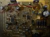
I've dismantled the subwoofer and amplifier. The transformer is giving out 15V, and is labeled for 13.5V. I can't see any burnt out components on the pcb. The only thing I see that's different is a component labeled "TFA9842J", wich has a kind of white paste on it's back, but i assume that's some kind of thermal paste.
I've also dismantled the remote volume control and there doesn't seem to be anything wrong with it either.
If needed I can post some pictures of the pcb, remote volume control, etc..
What should I do?
Thanks in advance
 
Last edited:

Gryd3

Jun 25, 2014
4,098
Joined
Jun 25, 2014
Messages
4,098
Each one of the components will need to communicate somehow. Following these lines helps after making sure power is being distributed properly.
Do you have any pictures or a model number? It sounds as though the remote, and both speakers plug directly into the sub and have their own socket for such a thing.
 

roberto8978

Sep 6, 2014
12
Joined
Sep 6, 2014
Messages
12
Each one of the components will need to communicate somehow. Following these lines helps after making sure power is being distributed properly.
Do you have any pictures or a model number? It sounds as though the remote, and both speakers plug directly into the sub and have their own socket for such a thing.

Gryd3
Thanks for your reply Gryd3. The first picture has the amp on the left and the remote volume control on the right. The 4th picture shows that "white past" I was talking about, and the last photo shows the socket for the pair of speakers (not the subwoofer speaker).
I'm really just starting to introduce myself to electronics, so pardon my ignorance, but how do I make sure that the power is being distributed properly?
 
Last edited:

Gryd3

Jun 25, 2014
4,098
Joined
Jun 25, 2014
Messages
4,098
You have located the power line already. The input looks to be AC, I am unsure what voltage. This feeds through a fuse and those four diodes that are used to rectify the AC voltage to DC.

To measure the AC side, set your meter to AC and measure where the power from the transformer comes in.
To measure the DC side, set your meter to DC and make note of the 4 diodes near the fuse. They are setup in pairs. You can take your meter and put one probe on the right diode, and the other on the left. Touch the diode's wire that is facing the capacitor.
That capacitor may be charged though, so be cautious and if you have clips for your meter's probes, use them. If clips are out of the questions, try with one hand just in case you short the capacitor, you dont want to have one hand on each probe.
 

roberto8978

Sep 6, 2014
12
Joined
Sep 6, 2014
Messages
12
You have located the power line already. The input looks to be AC, I am unsure what voltage. This feeds through a fuse and those four diodes that are used to rectify the AC voltage to DC.

To measure the AC side, set your meter to AC and measure where the power from the transformer comes in.
To measure the DC side, set your meter to DC and make note of the 4 diodes near the fuse. They are setup in pairs. You can take your meter and put one probe on the right diode, and the other on the left. Touch the diode's wire that is facing the capacitor.
That capacitor may be charged though, so be cautious and if you have clips for your meter's probes, use them. If clips are out of the questions, try with one hand just in case you short the capacitor, you dont want to have one hand on each probe.
Once again, thank you for the help Gryd3
The AC coming in from the tranformer is set at 15V.
The DC side shows a value of 20V
 

Gryd3

Jun 25, 2014
4,098
Joined
Jun 25, 2014
Messages
4,098
OK Can you please snap another picture of the top and the bottom of the board with the flash off... the glare makes it pretty hard to see. Bottom of the remote would also help
https://www.electronicspoint.com/resources/how-to-take-photos-of-circuit-boards.6/

There are two little 8 legged ICs on the board as well. I can make out one of them, but if the picture does not clearly show, can you please tell us the marking on each.
Please also tell us the markings on each of the white pasted items. (Were these components against metal prior to disassembly?)

Next step is to identify some of the more complex items used so we know what pin is supposed to do what. The new pictures will help to follow the traces on the bottom of the board to find out what components the power goes to.

Just to clarify. Are any of the capacitors bulging slightly?
 

KrisBlueNZ

Sadly passed away in 2015
Nov 28, 2011
8,393
Joined
Nov 28, 2011
Messages
8,393
Service information would be pretty helpful. Do you have a model number we could Google? It's unlikely, but possible, that there's a schematic or even a service manual available somewhere out there.

Have a good close look at the underside for dry joints. These happen often on single-sided non-plated-through boards, especially on components that get hot, such as the "TFA9842J" power amplifiers, and on connectors, especially on end pins. But check everything carefully. Any large or suspect components, wiggle it slightly and gently from above while watching the leads on the underside to see whether anything is not firmly connected.

The data sheet for the power amp ICs is available at http://www.nxp.com/documents/data_sheet/TFA9842J.pdf and it shows the VCC and GND pins (9 and 5) which should have the DC voltage you measured across the main electrolytic between them. If that voltage is present on both, you can work from there. But service information would really help.
 

roberto8978

Sep 6, 2014
12
Joined
Sep 6, 2014
Messages
12
P8190520.JPG
OK Can you please snap another picture of the top and the bottom of the board with the flash off... the glare makes it pretty hard to see. Bottom of the remote would also help
https://www.electronicspoint.com/resources/how-to-take-photos-of-circuit-boards.6/

There are two little 8 legged ICs on the board as well. I can make out one of them, but if the picture does not clearly show, can you please tell us the marking on each.
Please also tell us the markings on each of the white pasted items. (Were these components against metal prior to disassembly?)

Next step is to identify some of the more complex items used so we know what pin is supposed to do what. The new pictures will help to follow the traces on the bottom of the board to find out what components the power goes to.

Just to clarify. Are any of the capacitors bulging slightly?
P8190497.JPG P8190510.JPG P8190502.JPG P8190505.JPG
So, in case it's not readable in the pictures, the IC's are both marked utc4558 and the white pasted items are marked TFA9842J. The TFA9842J were in fact against metal prior to disassembling. As far as I can see, there are no capacitors bulging.
Ont the last picture is the bottom of the volume control. The three middle pins (from the nine on the top) connect to the jack that plugs into the pc. the rest comes from the pcb.
Thanks for your help,
Roberto
 

roberto8978

Sep 6, 2014
12
Joined
Sep 6, 2014
Messages
12
Service information would be pretty helpful. Do you have a model number we could Google? It's unlikely, but possible, that there's a schematic or even a service manual available somewhere out there.

Have a good close look at the underside for dry joints. These happen often on single-sided non-plated-through boards, especially on components that get hot, such as the "TFA9842J" power amplifiers, and on connectors, especially on end pins. But check everything carefully. Any large or suspect components, wiggle it slightly and gently from above while watching the leads on the underside to see whether anything is not firmly connected.

The data sheet for the power amp ICs is available at http://www.nxp.com/documents/data_sheet/TFA9842J.pdf and it shows the VCC and GND pins (9 and 5) which should have the DC voltage you measured across the main electrolytic between them. If that voltage is present on both, you can work from there. But service information would really help.
Thanks for your help KrisBlueNZ!
This is a set of logitech x-210 speakers
I hope that the following pictures show the model number you were asking me:
P8190522.JPG P8190523.JPG


I found this on one of the TFA9842J, is it a dry/bad joint?P8190509.JPG
 

roberto8978

Sep 6, 2014
12
Joined
Sep 6, 2014
Messages
12
I also checked the voltage of both TFA9842J components, by connecting a probe to the fifth pin and the other probe to the 9th, and the reading is of 19.7V (same on the two of them)
 

KrisBlueNZ

Sadly passed away in 2015
Nov 28, 2011
8,393
Joined
Nov 28, 2011
Messages
8,393
Oh, X-210 is the model number! Sorry. Thanks for the photos.

OK, so the output ICs have their 20V DC supply voltage. That's a good start!

I don't see anything wrong with those joints on those pins, but if you're not sure, you could resolder them. This is actually best done when the ICs are mounted back onto their metal heatsink, but you will have to delay reattaching them to their heatsink if that would make it impossible to access the circuit board.

For each pin, with the soldering iron on one side and the solder coming in from the other side, press the soldering iron gently against the bottom of the pin where it meets the circuit board. Once the existing solder melts, feed some new solder into the L-angle between the pin and the board on the opposite side from the soldering iron, so that it flows around the pin. Quickly remove the solder, then the soldering iron, and leave the board without moving or bumping it for at least ten seconds. Then move on to the next pin.

I can't find any service information, but we know the pinouts for those ICs. We need to know how those output ICs are used though. One of them will be used as a stereo amp, for the left and right speakers, and the other will be used as a mono amp, in bridge-tied load configuration (BTL), for the subwoofer.

You can check the DC voltages on some pins of the TFA9842J ICs. They should be about the same on both ICs.

Pins 2, 6, and 8 should all be about half the supply voltage, i.e. about 10V.

Pin 7 should be at least 2V. If it's less than that, the device is being held in mute or standby mode.

You can also check for power supply voltage on the two 4558 ICs. Pins are numbered from 1 to 8 anticlockwise (looking down on the IC from above), starting with the pin anticlockwise of the semicircular indentation, like this:
dip-8 dual op-amp.jpg
Pin 8 on both of them should measure at least +12V, probably close to +20V. Pin 4 on both of them should measure 0V.

All of these voltages should be measured relative to the 0V rail of the circuit. This is the large tinned copper area that I've highlighted in blue on this photo. You can connect your multimeter black lead to any component that connects to that copper. I suggest you use one of the four large diodes in the bridge rectifier in the power supply section.

0v highlighted.jpg
 

roberto8978

Sep 6, 2014
12
Joined
Sep 6, 2014
Messages
12
So i guess you have found the problem Kris Blue NZ. The TFA9842J ICs are not showing correct voltage values. Pins 2,6,7 and 8 show a voltage of 0V on both IC's, except for pin6 on one of them that shows a value of 0.2 v
On the other IC's there is a voltage of 12.2V on pins 8 and a voltage of 0V on pins 4(so i guess they aren't the problem).
I'm gonna now try to resolder the joints for the pins of the malfunctioning IC's. But in case they still don't work properly, should I just replace them?
 

Gryd3

Jun 25, 2014
4,098
Joined
Jun 25, 2014
Messages
4,098
Thanks for jumpin' in Kris. You've got more tricks than I do ;)
 

roberto8978

Sep 6, 2014
12
Joined
Sep 6, 2014
Messages
12
So i guess you have found the problem Kris Blue NZ. The TFA9842J ICs are not showing correct voltage values. Pins 2,6,7 and 8 show a voltage of 0V on both IC's, except for pin6 on one of them that shows a value of 0.2 v
On the other IC's there is a voltage of 12.2V on pins 8 and a voltage of 0V on pins 4(so i guess they aren't the problem).
I'm gonna now try to resolder the joints for the pins of the malfunctioning IC's. But in case they still don't work properly, should I just replace them?
well so I resoldered the joints on the TFA9842J ICs and something weird happened. The first reading I did showed a reading of 10V on pins 2,6 and 8; and 6V on pin 7.
However, after unplugging, waiting a few seconds and replugging, the readings went back to 0 on those pins. Only pin 9 still shows a voltage of 20V
 

KrisBlueNZ

Sadly passed away in 2015
Nov 28, 2011
8,393
Joined
Nov 28, 2011
Messages
8,393
It seems unlikely that both power amp ICs would fail. Pin 7 of each output IC is the mute/standby control input. These inputs on the two output ICs are connected together. Check this voltage; if it's more than 2V lower than the supply voltage on pin 9 (the 20V rail), the output ICs are being held in mute or standby.

This signal appears to come from the wire that connects at the front of the board. I traced it from the output ICs, through a link wire that's obscured by the red/black wires, then through a link wire called JMP4, and through another called JMP1 which is just north-west of the area where the wire enters the board. From there, it appears to go to the fourth pad (counting from the left) of the wire connection. You'll need to find where that wire goes, to figure out why the voltage is wrong. If you can't figure it out, you could just remove one of those wire links and tie those IC inputs to the 20V supply rail.

Edit: BTW you did a great job with those photos! The two sides line up almost perfectly with no adjustment. That has made it very easy for me to follow the signals.
 

Gryd3

Jun 25, 2014
4,098
Joined
Jun 25, 2014
Messages
4,098
Edit: BTW you did a great job with those photos! The two sides line up almost perfectly with no adjustment. That has made it very easy for me to follow the signals.
Agreed. Wonderful job. I stuck the two pictures together and did a minor tweak. This is why clear pictures helps ;)
 

Attachments

  • Untitled.jpg
    Untitled.jpg
    155.4 KB · Views: 610

roberto8978

Sep 6, 2014
12
Joined
Sep 6, 2014
Messages
12
Thank you on your compliments gentlemen. I seem to have found the REAL problem. I followed the path that krizblue NZ pointed out to me and I found out that it went to one of the cables that connected to the volume control (one of six). In order to further assess the situation, I had to remove the hot glue that was around those same wires on the pcb. The result was that I pried almost all of them out while doing this, but I managed to resolder them into the pcb. I pluged it in, and again... the LED didn't come on (I checked the LED and it's working). So I remembered: Why not do a continuity test of these wires between the volume control terminal and the pcb terminal. It seems that the blue wire is broken somewhere along the cable (all the others wires seem to be OK). And that wire connects to the switch that turns the power on. I guess that the best way would be to deattach this one cable from both ends and put in a new one, and just wrap it around the main cable (wich inside has the remaining 5 tiny cables --- that establish the connection between the pcb and the volume control+switch --- and the broken tiny blue cable) and just leave that same blue one there, isolating it's tips to avoid short circuits. Any better suggestions?
 

Gryd3

Jun 25, 2014
4,098
Joined
Jun 25, 2014
Messages
4,098
Thank you on your compliments gentlemen. I seem to have found the REAL problem. I followed the path that krizblue NZ pointed out to me and I found out that it went to one of the cables that connected to the volume control (one of six). In order to further assess the situation, I had to remove the hot glue that was around those same wires on the pcb. The result was that I pried almost all of them out while doing this, but I managed to resolder them into the pcb. I pluged it in, and again... the LED didn't come on (I checked the LED and it's working). So I remembered: Why not do a continuity test of these wires between the volume control terminal and the pcb terminal. It seems that the blue wire is broken somewhere along the cable (all the others wires seem to be OK). And that wire connects to the switch that turns the power on. I guess that the best way would be to deattach this one cable from both ends and put in a new one, and just wrap it around the main cable (wich inside has the remaining 5 tiny cables --- that establish the connection between the pcb and the volume control+switch --- and the broken tiny blue cable) and just leave that same blue one there, isolating it's tips to avoid short circuits. Any better suggestions?
Good job on the find there.
Caution should be used if you replace the cable, as it does appear to carry audio and using the wrong cable could pick up noise.
I've got three suggestions, we'll see what Kris thinks.
Add an additional wire and run it along side the current cable.
Use Cat6 ethernet cable and replace the whole cable. * (my pick, carefully using the pairs to carry audio to reject noise that may be picked up by using unshielded cable)
Simply add a push button or toggle on the amp to bypass the blue wire.
 

KrisBlueNZ

Sadly passed away in 2015
Nov 28, 2011
8,393
Joined
Nov 28, 2011
Messages
8,393
I wouldn't use Ethernet cable; it should be shielded. I'd go with Roberto's suggestion in post #18 - add another wire, either spiralled around the existing cable or held to it with rubber bands or cable ties, to replace the broken one.
 
Top