First of all i would like to say hello to all of you as it's my first post here.
I came here because obviously i need help. To be more specific i'm working with a circuit that will act something like wireless/touchless switch.
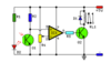
I have those 2 schematic. Schematic 1 is the one i'm basing on my project and 2nd is what modifications i've done.

D2 is a IR diode
IC1 is a CA3140 op amp ( in lt spice i used a universal op amp)
Q2 is replaced by the suggestion of teacher on MOSFET transistor ( still dont know which one exactly i need to use)
Q1 is a phototransistor ( in lt spice schematic it'a current source because it's easier to implement it there)
R4 is a potentiometer used to set a sensivity (in lt spice i did a voltage divider because of same reason as Q1)
I replaced D1 and RL1 by inserting a diode

Here i added a D flip flop.
The working principle i'm planning to achieve is when voltage source of 5 V is connected, a IR diode emits it's rays on phototransistor (right?) Q1 and when u pass a hand over IR Diode it should light up the LED behind mosfet and when you pass a hand 2nd time over IR diode it will switch off. Dflop is here to provide such an action.
Next for what i've already searched on and i think i know that when hand is passed over IR Diode pin 3 non inverting it's turning into high state right?. Pin 2 - inverting is connected to potentiometer and it works only for sensivity (right?) So now a result of turning pin 3 ino high state the signal goes on a pin6 output and it is remembered by d flop and led is lighted up and so turn it off second hand move is needed?
I don't know if i explained it well but thanks for any help.
I came here because obviously i need help. To be more specific i'm working with a circuit that will act something like wireless/touchless switch.
I have those 2 schematic. Schematic 1 is the one i'm basing on my project and 2nd is what modifications i've done.
D2 is a IR diode
IC1 is a CA3140 op amp ( in lt spice i used a universal op amp)
Q2 is replaced by the suggestion of teacher on MOSFET transistor ( still dont know which one exactly i need to use)
Q1 is a phototransistor ( in lt spice schematic it'a current source because it's easier to implement it there)
R4 is a potentiometer used to set a sensivity (in lt spice i did a voltage divider because of same reason as Q1)
I replaced D1 and RL1 by inserting a diode
Here i added a D flip flop.
The working principle i'm planning to achieve is when voltage source of 5 V is connected, a IR diode emits it's rays on phototransistor (right?) Q1 and when u pass a hand over IR Diode it should light up the LED behind mosfet and when you pass a hand 2nd time over IR diode it will switch off. Dflop is here to provide such an action.
Next for what i've already searched on and i think i know that when hand is passed over IR Diode pin 3 non inverting it's turning into high state right?. Pin 2 - inverting is connected to potentiometer and it works only for sensivity (right?) So now a result of turning pin 3 ino high state the signal goes on a pin6 output and it is remembered by d flop and led is lighted up and so turn it off second hand move is needed?
I don't know if i explained it well but thanks for any help.