Maker Pro
Maker Pro

Need help with wiring 120 to 220 all schematics here

Obetech

Feb 21, 2017
5
Joined
Feb 21, 2017
Messages
5
I bought that unit and its like dual 120 or 220 but no switch. Have to resolder jumper.
 

Attachments

  • IMG_0363.JPG
    IMG_0363.JPG
    325.1 KB · Views: 80
  • IMG_0598.PNG
    IMG_0598.PNG
    323.8 KB · Views: 103
  • IMG_0600.PNG
    IMG_0600.PNG
    470.8 KB · Views: 80
  • IMG_0601.JPG
    IMG_0601.JPG
    289.2 KB · Views: 78

shrtrnd

Jan 15, 2010
3,876
Joined
Jan 15, 2010
Messages
3,876
The figure 3.2 seems pretty clear to me, what don't you understand?
You're in the UK (240V mains), so I assume you bought the unit wired for operation in the US (120V mains).
If I'm correct in that assumption, you need to remove the jumpers between terminal 1 & 4, and 3 & 6; and then install
a jumper between terminals 4 & 3.
Are you unsure of the terminal locations or designations, or what exactly don't you understand?
 

Obetech

Feb 21, 2017
5
Joined
Feb 21, 2017
Messages
5
Hi, yes Im unsure of that terminal location 4&3. could you help with this please.

Thank you
 

Obetech

Feb 21, 2017
5
Joined
Feb 21, 2017
Messages
5
Ps. Im not professional electronic guy, but not stupid lad ;), im musician with good soldering skills.... :) just would like to know where to to solder that jumper.
 

shrtrnd

Jan 15, 2010
3,876
Joined
Jan 15, 2010
Messages
3,876
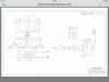
The numbers on figure 3.2 are supposed to match the numbers on the transformer picture.
When you flip the board over to where the transformer is soldered to the printed circuit board, you're supposed to cross reference the corresponding numbers on the transformer to the solder points under the board.
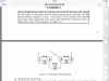
Looking at your bottom board picture (right side of picture, bottom)
You have three solder points which are the 3-pin connector.
Above the 3 pin connector you have from left to right, four of the transformer connections, in order from left to right, 1 , 2, 4, 3. (when you turn the board over you can verify that they match the numbers on the transformer).
You can see in your underside solder-point picture that above those four solder points, you have four more solder
points that correspond to the transformer connections (again from picture left to right 5, 6, 8, 7).
Looking at the underside picture, the solder point jumper wires DO NOT match the transformer numbering points in Figure 3.2
(Which is why you're probably posting your question here).
Either somebody replaced the originally specified transformer at some point, or you have a REVISION of a unit that
your manual does not match.
I don't have the time to do it, but you have the installed transformer's identification:
Sigma Transformer 'Flathead' LP-40-300, there's probably technical data on that available on the web.
I, would contact the unit manufacturer of your device, tell them the issue, and ask for a remedy.
My guess is, your actual unit is not the one figure 3.2 was written for.
Somebody else here might be able to research your problem, but the more information you can get about the unit
you have, and the manufacturer's recommendation for converting it from 120VAC to 240VAC, would help you
or us solve this dilemma.
Figure 3.2 is clear. It just doesn't match your actual transformer wiring.
You'll need to know how that transformer is wired to do this, and a spec sheet is what's needed; or if this was a
factory installed replacement during some manufacturing revision, what the manufacturer recommends.
My magic wand won't tell me the transformer configuration/voltages from here.
 

Obetech

Feb 21, 2017
5
Joined
Feb 21, 2017
Messages
5
Thank you very much for answer,

This is reply from manufacture:

I am attaching schematics for the most recent SPM 220 and the older SPM 2 and SPM 3. Your unit may be different (if so, the SPM 2 3 schematics may be closer to what you have). All units used the same transformer. The newer units have an AC mains voltage select switch. The wiring diagram for the SMP 2 3 is on page 5 of the SPM 2 3 manual (attached).

John Siau
 

Attachments

  • SPM 2and3 Manual.pdf
    404.4 KB · Views: 217
  • Comp Layout.pdf
    258.5 KB · Views: 69
  • SPM 2 3 sht 1 v36 scm.pdf
    44.5 KB · Views: 44
  • SPM 2 3 sht 2 v36 scm.pdf
    39.3 KB · Views: 62
  • SPM 2 3v36 scm.pdf
    74.3 KB · Views: 67
  • SPM 2 3v36-1.pdf
    63.7 KB · Views: 47
  • SPM-220_320 Schematic RevC P1.pdf
    173.3 KB · Views: 46
  • SPM-220_320 Schematic RevC P2.pdf
    85.4 KB · Views: 51
  • SPM-220_320 Schematic RevC P4.pdf
    90 KB · Views: 43
  • SPM-220_320 Schematic RevC P3.pdf
    69.9 KB · Views: 48

shrtrnd

Jan 15, 2010
3,876
Joined
Jan 15, 2010
Messages
3,876
Good, sounds like they want to help.
It's also good that they say they all use the same transformer, so it's a matter of finding the correct terminal
diagram, as the original Figure 3.2 you showed does not match what the board is wired for.
So. Do you have the Model SPM2, SPM3, or the SPM 220 (or some other one)?
I'm on my way out the door for the day here.
Hopefully somebody else will answer you with your follow-up answers while you're still on.
Otherwise I won't be back on the computer until sometime tomorrow.
If you look over what the manufacturer sent you, try to find the information on rewiring the input power for
220V, from the 120V you believe it is presently wired for.
You'll need to match your model number to the correct data sheet they sent you.
Heck. If you sent them the same pictures you posted here, they probably could have given you the directions
right then and there.
Don't get discouraged, people here are only on this site intermittently, and can't always get back to requests
as quickly as we wish we could.
 

Obetech

Feb 21, 2017
5
Joined
Feb 21, 2017
Messages
5
Thank you so much, I have spm 220 model. And yes Ive sent them same pic as here. As im not electronic guy and dont want to damage it... will wait for answers which pins to solder.

Thank you very much
 

shrtrnd

Jan 15, 2010
3,876
Joined
Jan 15, 2010
Messages
3,876
I'm back. Sorry nobody else joined the conversation to help you out while I was gone.
I'm working my job right now, but I'll take a look at what you got from the manufacturer in my down-time.
This will take a while, but wanted to let you know I'll get back to you on this as soon as I can.
I know waiting is frustrating, but I don't want to see any damage to your unit either.
 

shrtrnd

Jan 15, 2010
3,876
Joined
Jan 15, 2010
Messages
3,876
I'll give you my logic-reasoning explanation below, but it looks to me like your unit IS ALREADY wired for 240V mains, as is:
I checked the drawings the mfgr sent you, they were written by different guys, and it's obvious to me that they
were not using the same correlating data on the transformer lead numbering system.
So, I downloaded the transformer data from Signal Transformer (your model LP-40-300).
Your drawing #300-00055-001 shows the new installation of the 120V/240V switch, but a very different component configuration on the board (from what you actually have).
I ASSUME that the board you have was designed for the text in the manual that you posted. But I can't verify that, only the manufacturer can (so you might consider re-contacting them again for verification).
Using the data from the transformer manufacturer, and the picture of the actual board you posted:
YOUR wiring connects 'like polarity' transformer leads 1 & 3 together, and also 'like polarity' leads 2 & 4.
Each of those points connected to the 3-conductor mains power input connector, (center pin is ground).
That's the 240V mains connection made by 120V/240VAC switch S4 on drawing 450218)
If you had a 120v mains input, according to the manual text you posted, transformer leads 2 & 3 would be connected together, and they are not on your board. (See the 120V switch selection shown on Drawing 450218). Therefore, it looks like you presently have a 240V input configuration.
A 120V input wiring would be one side of the mains input connected to transformer lead #1, transformer leads #2 & #3 would be jumpered together, and the other side of the mains input would be connected to transformer lead #4
I won't go into all the head-scratching I did trying to figure out why the manual Figure 3.2 transformer wiring shows a
primary connection to secondary winding pin 6. Usually that's due to some engineer referencing some other connection point in the circuit that's further down the circuit trace (and he just references that in his mind).
With the transformer data sheet in my hands, I don't see anything else I can do except to arrive at the conclusion that your unit is already wired for 240VAC mains.
If you're still unsure about this and decide to re-contact the manufacturer of your SPM-220, you should also supply
them with the serial number of your unit (It'll be on some identification plate on the instrument), as that will tell
the manufacturer exactly what your model circuit configuration is (Besides your original, there have been at least
3 revisions of the original design).
Hope this helps. If you have any other questions about this, I've got the schematics and drawings you posted in
front of me and I can tell you what I see. They just don't match your original board layout.
 
Last edited:
Top