Maker Pro
Maker Pro

Need suggestion on whether the PCB design is correct

Farukh Khan

Jun 12, 2015
160
Joined
Jun 12, 2015
Messages
160
Hello Guys,

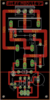
About a year ago I designed a simple one channel Relay Board PCB. I am about to manufacture couple of boards using PCBWay. So, I was wondering if you guys can check the PCB design and see if anything can be improved or any mistake was made in the design which needs to be corrected before manufacturing. Please help me out here so that I can proceed with the manufacturing. The relay specification is 250VAC@10A@50Hz. So, the relay module will also be used under that specification.

Link to full repo: https://github.com/uGiFarukh/Relay-Module


Thank You.
 

Harald Kapp

Moderator
Moderator
Nov 17, 2011
13,728
Joined
Nov 17, 2011
Messages
13,728
I wonder about the contact side of your design:
upload_2018-12-5_7-52-14.png
Obviously you intend to connect the load to X1-1 and the AC input to X1-2 (X1-3 is not used).
The contact has two possible positions marked in red and green by me.
green (P-O): the load is connected to the AC-input via R-AC and CAC.
red (P-S): the load is connected to the AC-input via the relay contact.

What is the use of R-AC and CAC in the 'green' position?
 

Farukh Khan

Jun 12, 2015
160
Joined
Jun 12, 2015
Messages
160
"What is the use of R-AC and CAC in the 'green' position? "It is the connection inside relay. And the RAC and CAC is there as a snubber circuit to protect the relay contacts while switching.
 

Harald Kapp

Moderator
Moderator
Nov 17, 2011
13,728
Joined
Nov 17, 2011
Messages
13,728
In that case I see nothing wrong with the circuit.
 

Farukh Khan

Jun 12, 2015
160
Joined
Jun 12, 2015
Messages
160
My main concern is with the PCB traces on the AC part. For 250VAC@10A@50Hz load will I get any interference or weird oscillation other than pure sine wave on the AC side?
 

Harald Kapp

Moderator
Moderator
Nov 17, 2011
13,728
Joined
Nov 17, 2011
Messages
13,728
It is difficult to judge the PCB artwork without knowing where the components go. An image with traces and component outlines and component designators (names) will be much easier to check.
 

Farukh Khan

Jun 12, 2015
160
Joined
Jun 12, 2015
Messages
160
the whole PCB eagle file is in that github repo. you can download it and check from there.
 

Harald Kapp

Moderator
Moderator
Nov 17, 2011
13,728
Joined
Nov 17, 2011
Messages
13,728
I'd have to install Eagle first which I will not do, sorry.
 

(*steve*)

¡sǝpodᴉʇuɐ ǝɥʇ ɹɐǝɥd
Moderator
Jan 21, 2010
25,510
Joined
Jan 21, 2010
Messages
25,510
I would have placed the fuse in series with the common connection to the relay. The way you have it, there is protection only for the N.O. contacts.

I would consider moving the resistor over a little to provide more distance between mains and low voltage wiring.

It may also be sensible to use the silk screen layer to delineate high and low voltage parts of the board.
 
Top