Hello everyone as mentioned in the thread title I am a new member and have been doing some research all over the internet and most of my results keep bringing me back to this site so I figured I would join and start asking some questions.
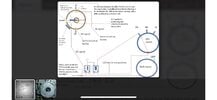
I have a project that I am currently trying to figure out and have found some info and really want to run it by some professionals. I am currently modifying a truck of mine and am using a transfer case that is controlled electrically. The motor of course is a 12v motor with a sensing ring inside that will be controlled by a factory switch from inside. I am needing this circuit to be able to swap polarity for the motor. It turns clockwise the to go from 2WD to 4wd high then 4wd low normal polarity then swap polarity and go from 4wd low to 4wd high then 2WD. So when the sensing ring sees it at a certain position (4wd high) it will stope the motor. The same for every position forward and reverse. I did come across a drawing that someone had made but would like some insight of it.
I have a project that I am currently trying to figure out and have found some info and really want to run it by some professionals. I am currently modifying a truck of mine and am using a transfer case that is controlled electrically. The motor of course is a 12v motor with a sensing ring inside that will be controlled by a factory switch from inside. I am needing this circuit to be able to swap polarity for the motor. It turns clockwise the to go from 2WD to 4wd high then 4wd low normal polarity then swap polarity and go from 4wd low to 4wd high then 2WD. So when the sensing ring sees it at a certain position (4wd high) it will stope the motor. The same for every position forward and reverse. I did come across a drawing that someone had made but would like some insight of it.