Maker Pro
Maker Pro

Nixie tube clock: display flickering, buzzer crackling

jacktron

Jan 14, 2017
3
Joined
Jan 14, 2017
Messages
3
Hello everyone. I have a IN-14 Nixie tube clock I built from a kit back in 2012 that is suddenly having a problem today (1/13/2017). I don't expect this problem to be solved, but I was just interested in posting a video seeing what experts and fellow electronics enthusiasts thought the problem could be related to, to perhaps get me on a better track to finding a fault. Any suggestions are very welcome.

Video showing the problem (with audio):


I know the life of these old IN-14 tubes is short and I was not expecting them to last this long. However, the tubes themselves are still lighting up fine and the symptoms of this issue *seem* unrelated to a tube's useful life ending. The problem happened when I was pressing a button as described below:

Today, I was attempting to set the time on the clock and in the middle of repeatedly pressing down one of the buttons to advance the "minutes," all 6 tubes suddenly began displaying random numbers extremely fast, and flickering in sync with each other. The buzzer on the board also started making a persistent clicking/crackling sound (similar to a Geiger counter).

The synchronized flickering resembles (to me, not an expert) a short in the AC adapter/cord or a crossed connection etc., but I'm not sure what to make of the constantly randomized/cycling digits or the continously crackling buzzer.

I disconnected the AC adapter from the clock, and everything turned off but the buzzer continued to make noise for ~20 minutes. Plugging it back in, the tubes immediately lit up and resumed cycling(?)/displaying random digits at an ultra-fast rate while flickering in sync with each other.

Other notes:
  • There are also 6 LEDs on the board, but they are steadily lit when switched on as opposed to the tubes and buzzer.
  • There is no smell I can detect.
  • The clock itself is merely an exposed board on 4 small metal legs. I can imagine anything from dust to moisture getting in the wrong place causing problems, but the clock has never had any type of problem until today while I was trying to set the time.
  • Because of the exposed components (including capacitors close to the buttons/switches), I am always very careful and deliberate when I am setting the time. I checked thoroughly to see if I accidentally bumped anything or caused any parts to touch, but I can't find anything so far. I haven't ruled out two parts touching, however, as the components are tightly packed and there are areas where solder points come close to touching.
  • Pressing the time set buttons again has no discernible effect on the tubes or the buzzer (it does seem to change what's displayed on the tubes, but they're so erratic I can't see any pattern).
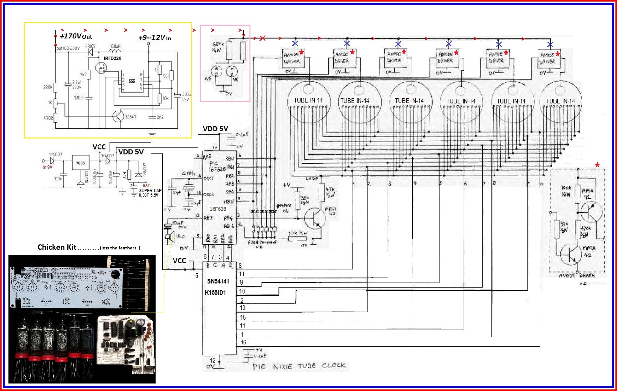
  • There is a microcontroller (PIC16F628A) on the board. I wondered if a failure could cause the strange behavior of the tubes in the video?
I imagine there are tons of possibilities and I'm sure I haven't provided enough information for a definite answer, but if the attached video looks like a certain "type" of problem in particular or if anyone has an idea of something to check out/investigate, please feel free to reply with any suggestions.

Thank you!
 

Harald Kapp

Moderator
Moderator
Nov 17, 2011
13,727
Joined
Nov 17, 2011
Messages
13,727
As this happened when you were pressing the button, I imagine a problem with a bad solder joint in the high voltage section of the circuit. This (or probably more than one) solder joint is likely having intermittend contact which leads to arcing. The electric arc, however small, ionizes air which expands and makes the crackling noise. At the same time the voltage and/or current that arrives at the tubes is interrupted which creates the flickering effect.

Remove power and wait some time to discharge all capacitors from high voltage (if you're unsure, a good night's sleep should be long enough). Then inspect all solder joints (other joints may be affected, too, without showing a prominent effect). re-solder those joints that look suspicious using quality fkux core solder. If you have a de-solder pump or solder wick, remove the old solder before re-soldering. Otherwise use new solder sparingly to avois big solder blobs.
 

(*steve*)

¡sǝpodᴉʇuɐ ǝɥʇ ɹɐǝɥd
Moderator
Jan 21, 2010
25,510
Joined
Jan 21, 2010
Messages
25,510
The sound is allegedly coming from a buzzer on the board.

However I concur with Harald's suggestion.
 

jacktron

Jan 14, 2017
3
Joined
Jan 14, 2017
Messages
3
Thank you so much. I'll do what you suggested, Harald, and hope I am able to locate the problem. I hadn't even thought about ionized air. It does sound to me like the crackling is coming from the center of the buzzer (there is just a hint of a "chirp" in the sound every now and then), but I'm definitely not sure, so I'm glad I asked about it here!

I'm also glad there is at least some chance I can repair it. I was worried someone might tell me immediately that some component(s) on the board had been "fried" and was unfixable—which, I assume is still a possibility.

I'll add that I'm almost positive this device wasn't put together 100% correctly in the first place due to 1. My lack of expertise/shaky soldering hands and 2. there were almost no instructions included with the kit, mainly a parts list and about 12 photos of different stages of the build process (and I believe some text in Lithuanian). I'm amazed I haven't encountered any issues until now, after ~4-5 years of perfect operation and many time/date/alarm/settings changes. Hoping to repair rather than simply build a new and improved clock (sentimental value + Nixie tubes are no longer in production anywhere in the world as far as I know).
 

(*steve*)

¡sǝpodᴉʇuɐ ǝɥʇ ɹɐǝɥd
Moderator
Jan 21, 2010
25,510
Joined
Jan 21, 2010
Messages
25,510
Take some clear photos of both sides of the board and anything else you think we might be interested in. The photos need to be good enough that we can read the markings on the board and on components.
 

hevans1944

Hop - AC8NS
Jun 21, 2012
4,882
Joined
Jun 21, 2012
Messages
4,882
A schematic diagram, if you have one, could also be helpful.

I agree with Harald: suspect ALL the solder joints since you were a newbie with shaky hands when you assembled this kit. Now that you hopefully have more experience with soldering, suck off the old solder with solder wick (one joint at a time) or use a hand vacuum de-soldering tool and then carefully apply small amounts of new 60% tin/40% lead rosin-core solder to each solder joint. Use a 40 W to 60 W pencil iron with a spade tip, not a "soldering gun". Then use a tooth brush and 91% isopropyl alcohol to scrub off and remove the solder flux residue, letting the alcohol drain off the edge of the board onto a towel until the whole board is clean. Be generous with the alcohol. Do not use "rubbing" alcohol; it has too much water content and is slow to evaporate. Your clock should be "as good as new" in a few hours if there is no component damage or cracks in the circuit board traces. Inspect the board with a strong back light and a magnifying glass to find any hair-line cracks in the circuit board. These can usually be repaired by bridging the crack with solder, or worst case with a short piece of fine gauge wire, usually just one strand removed from 16 to 24 AWG stranded "hook-up" wire.
 

73's de Edd

Aug 21, 2015
3,622
Joined
Aug 21, 2015
Messages
3,622
.


Sir jacktron . . . . . . .


I looked around and couldnt find your EXACT Lithuanian sourced ? unit, but found the same PCB look-a-likes being used on some RUSSKIE units.

Check out your unit against this schema and see if its basic design does also hold true on your specific unit.
I took SPECIAL interest in your video of the two s.t.r.e.t.c.h ed out electrodes of the quasi NE-2 lamps, that are being used as colon separators between digit set pairs, and that they were ALSO flickering , along with the very noticeable nixie display segments.

Now, by referencing the schematic . . . you can see that each one of them are being continually left on and that their power is fed by the ~170 VDC through a series dropping resistor for each.

The additional colon displays flickering, would therefore seem to be indicative of either an erratic 170 VDC supply source or some item also being fed by the power supply on downstream, is likely going into an intermittent / sporadic avalanching mode and erratically pulling down the 170VDC supply line.

If my problem to solve, I would initially refer to the supplied schematic mark ups, which will show that the 170VDC regulated supply source is being generated within the top left corners YELLOW box.
Its voltage supply follows the RED arrowed line and initially feeds the two neon lamps used as colon indicators.
Then the power flow is to the right to each of 6 discrete built up anode driver switching blocks (RED STARS) that are being component defined over to the right side as per their manner of build up.. . . . its marked with a RED STAR also.

NORMAL OPERATION . . . . .

of this unit would be having 170 VDC being initially fed to the individual neon colon indicators and then since this is a MULTIPLEXED display, pin 1 of the PIC16F628 u/p activates the MPSA42 transistor within the first anode driver block which then creates a base drive signal to its companion MPSA92 high voltage driver transistor.
That conduction has power completion to the anode of that first nixie tube . . . meanwhile, back in the jungle, at the SN54141 BCD-TO-DECIMAL DECODER/DRIVER, at its ABCD decoder inputs from the 16F628 u/p it is simultaneously receiving info to see which digit is supposed to be activated on that first nixie, and that 54141 chip completes the power loop to ground internally.

THEN the same procedure is repeated for the next nixie digit, on down thru the 6th nixie tube, THEN the whole sequence through the set of nixies, repeats again.
Since this rapid on and off sequencing through all of the digits is occurring quicker than the human eyes ~200 milliseconds response time of vision, a persistence of vision fools the eye, and it makes it seem like ALL of the digits are continually being displayed.
Should one of the MPSA92' s avalanche C to E , an adjunct voltage spike could travel backwards into the pins 6 thru 11 pins of the PIC16F628 u/p, as they also serve as address lines, when setting the clock through the 6 steering diode matrix, which you see sitting just below them.
That could then upset all counting sequences and produce totally irrelevent numbers and timing, or even drop counts.The current situation is even heard encroaching into the drive to the piezo speaker of the unit.

TESTING:

Trying to pinpoint those erratic voltage changes and drop outs could certainly be problematic , when attempting to use either an analog or DVM. . . . . by . . . slow metering indication response time.

Fortunately, you already have something encroaching upon a scopes analysis capability, in the form of those two neon colon indicators.

Note the RED X just past them, for the first test, open that circuitry at that point and power up then to see if the colons are being in a steady on condition, but they may be a bit brighter, due to no downstream supply load.

If the same prior flicker-flashee flashee still persists by them, the 170 VDC power supply is suspect and needs to be worked on.
If having a steady lit up set of colons, then restore the RED X broken connection and try the sequentially disconnecting of each of the BLUE X supply points one at a time.
That would isolate a bad circuit combination . . . . . . . likely expecting an anode driver ciruit block,

Thaasssssit . . . . .


RELEVANT VISUAL REFERENCING SOURCE :


NWogj7y.jpg


73's de Edd


.
 
Last edited:
Top