I originally posted a thread reguarding making an LED power source to drive 84 LEDs at 10v for a solar installation. https://www.electronicspoint.com/driving-leds-var-power-source-efficiency-t241211.html
I have heeded the advice given there and moved to a boost/buck regulator and brought up the overating voltage to 25.7v and moved to 80 LEDs instead (8x10 LEDs with a 4Ohm resister on each run).
Being that I am still very much a noob (last time playing with circuit design was a highschool class) and I do not have any components (will be ordering them later), I decided to lay the circuit out in LTSpice and run the simulation. The simulation took over 12 hours and when all was said and done, I'm not seeing what I think I should have seen.
My concern is this:
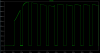
This circuit uses PWM (~100Hz) to allow LED dimming and yet adjusting the duty cycle seems to have no affect on the circuit's power consumption. The power consumption simulated to jump (AC style) very quickly (10 microsecond range) with an average of about 7.5W. There is no diffrence in simulated power draw between the LEDs being switched on or off. I would assume that with the simulation being as indepth as it is, there would be a differance shown, but nada.
Also - when the MOSFET is switched to turn power on or off there is a jump and or dip in current and voltage. What is a good way to smooth this out for the load to the LEDs are not getting such a blast on switching or is this just to be expected and is it damaging to the LEDs at all?
So here's my plea - 97% of people here are LESS noob than I and could probably shine some light on this in some manner (Maybe I'm just not looking at this right?) I have attached the schematic and some of the plots.
Thanks
I have heeded the advice given there and moved to a boost/buck regulator and brought up the overating voltage to 25.7v and moved to 80 LEDs instead (8x10 LEDs with a 4Ohm resister on each run).
Being that I am still very much a noob (last time playing with circuit design was a highschool class) and I do not have any components (will be ordering them later), I decided to lay the circuit out in LTSpice and run the simulation. The simulation took over 12 hours and when all was said and done, I'm not seeing what I think I should have seen.
My concern is this:
This circuit uses PWM (~100Hz) to allow LED dimming and yet adjusting the duty cycle seems to have no affect on the circuit's power consumption. The power consumption simulated to jump (AC style) very quickly (10 microsecond range) with an average of about 7.5W. There is no diffrence in simulated power draw between the LEDs being switched on or off. I would assume that with the simulation being as indepth as it is, there would be a differance shown, but nada.
Also - when the MOSFET is switched to turn power on or off there is a jump and or dip in current and voltage. What is a good way to smooth this out for the load to the LEDs are not getting such a blast on switching or is this just to be expected and is it damaging to the LEDs at all?
So here's my plea - 97% of people here are LESS noob than I and could probably shine some light on this in some manner (Maybe I'm just not looking at this right?) I have attached the schematic and some of the plots.
Thanks
Attachments
-
FULL_CIRCUIT-LTSpice.zip4.8 KB · Views: 90
-
 circuit-battery_power.png6 KB · Views: 169
 -
 circuit-resister_load.png6.2 KB · Views: 189
 -
 circuit-voltage_from_regulator-before_load.png5.6 KB · Views: 144
 -
 circuit-voltage_from_regulator-after_load.png5.3 KB · Views: 154
 -
 circuit-schematic.png43.7 KB · Views: 175
Last edited: