Maker Pro
Maker Pro

NPN circuit isn't switching after power change

MrJymm

Jan 29, 2017
2
Joined
Jan 29, 2017
Messages
2
Hi all, amateur here, with just enough knowledge and google-foo to get myself into trouble. Hoping for some help on why my circuit isn't working.

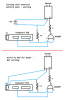
I'm working on a project that takes a sensor input and triggers a keystroke from a USB keyboard. I prototyped the circuit on a breadboard using an alternate battery power source and it worked great. But I always intended to wire the power to the USB line for the completed circuit, and now it won't trigger. I'm fairly certain there aren't any issues with the soldering or anything, testing the individual connections and components didn't give me any obvious failure points. I'm thinking the change to a single power source screwed up how the NPN switches, but I can't figure out how to address that.

Any help would be greatly appreciated!
 

Attachments

  • Sensor Circuit.png
    Sensor Circuit.png
    21.1 KB · Views: 125

CDRIVE

Hauling 10' pipe on a Trek Shift3
May 8, 2012
4,960
Joined
May 8, 2012
Messages
4,960
I'm a bit confused here as I see two things that don't make sense. For one thing the battery polarity is opposite of the ± input on your sensor. This is just probably a drawing error. My other issue is your USB keyboard. USB keyboards don't output 5V they input it from the computer's USB port. It certainly explains why it works with the battery supply. There's no reason it should work as drawn connected to the keyboard USB port.

Chris
 

davenn

Moderator
Sep 5, 2009
14,262
Joined
Sep 5, 2009
Messages
14,262
My other issue is your USB keyboard. USB keyboards don't output 5V they input it from the computer's USB port. It certainly explains why it works with the battery supply. There's no reason it should work as drawn connected to the keyboard USB port.

one of those eureka moments ;) :)
 

AnalogKid

Jun 10, 2015
2,893
Joined
Jun 10, 2015
Messages
2,893
When battery-powered, the ground references for the sensor and the keyboard are different. What is the sensor? manufacturer? Data sheet? What are the two rectangles within the USB rectangle?

ak
 

MrJymm

Jan 29, 2017
2
Joined
Jan 29, 2017
Messages
2
Thank you all for your input! Let me try and answer your questions and clarify where I'm at with the project.

If the battery symbol on the top image is backwards, that's just a drawing error. The circuit worked so it was wired correctly.

Also poorly drawn is the USB wiring. I've wired to the power pins of the keyboard's USB port to piggyback off the power it draws when plugged into the PC.

The sensor is this moisture sensor. It has two LEDs that show it is operating - One lights solid when it receives power, the other LED lights when the attached pad is wet. Both LEDs are working as connected to the 5V pins of the USB keyboard PCB as the power source.

The keyboard PCB was removed from a cheap keyboard. The two long rectangles are the pins that connect to the upper and lower wiring sheets that map out the keys and determine which one was pressed. Shorting any pin from the left to any pin from the right creates a keystroke.

The moisture sensor output is set high when powered. When the pad gets wet the output is low. When the output drops, the NPN switches to connect the right keyboard pin to the left, which creates the keystroke. That's exactly what happened during testing.

As wired in the bottom photo, the sensor is powered and working, and the keyboard can send keystrokes if I manually short contacts. The issue is that the transistor between the two never switches. This is where I'm not knowledgeable enough. From what I understand the NPN should switch when the voltage on B goes lower than the voltage on C. But something about using the same power source for both sides seems to have messed that up?
 

Alec_t

Jul 7, 2015
3,590
Joined
Jul 7, 2015
Messages
3,590
Your schematic shows the transistor collector connected via a resistor to the negative pin of the sensor instead of to the positive pin.
 

CDRIVE

Hauling 10' pipe on a Trek Shift3
May 8, 2012
4,960
Joined
May 8, 2012
Messages
4,960
When I clicked on your sensor link Norton blocked it reporting it to be a known DANGEROUS website??

Chris
 

CDRIVE

Hauling 10' pipe on a Trek Shift3
May 8, 2012
4,960
Joined
May 8, 2012
Messages
4,960
The 2N2907 is a PNP which leaves me to believe that your sensor output goes low when triggered. If that's the case your circuit should look like this.

Chris
upload_2017-1-30_10-13-12.png
 

CDRIVE

Hauling 10' pipe on a Trek Shift3
May 8, 2012
4,960
Joined
May 8, 2012
Messages
4,960
I forgot to mention that since I was unable to read the description of your sensor I'm also unable to determine if your output pin is relay contacts or possibly open collector logic. If either case is true you don't need the 2N2907 as the output pin can be directly connected (no resistor either) to the high side of the keyboard key.

Chris
 

davenn

Moderator
Sep 5, 2009
14,262
Joined
Sep 5, 2009
Messages
14,262
The 2N2907 is a PNP which leaves me to believe that your sensor output goes low when triggered. If that's the case your circuit should look like this.

Chris
View attachment 31662

Chris ... the 2N2907 is a NPN transistor ;)
sp you need to change the arrow direction and flip the device vertically
 

CDRIVE

Hauling 10' pipe on a Trek Shift3
May 8, 2012
4,960
Joined
May 8, 2012
Messages
4,960
Dave have you been tipping the glass a bit more today? :D

Chris
 

(*steve*)

¡sǝpodᴉʇuɐ ǝɥʇ ɹɐǝɥd
Moderator
Jan 21, 2010
25,510
Joined
Jan 21, 2010
Messages
25,510
My thought is that when the transistor was switched with an independent power source, it worked because whatever is being switched can have some undefined relationship with its own power rails. When you power it with the same rails as the device you may inadvertently connect a power rail somewhere that it shouldn't be.

My recommendation would be to use an optocoupler.

Edit: looking at your circuit, my reasoning above shouldn't be true, but...

Edit 2: Cdrive's circuit.
 
Last edited:

CDRIVE

Hauling 10' pipe on a Trek Shift3
May 8, 2012
4,960
Joined
May 8, 2012
Messages
4,960
OK, now that we've defined the transistor type has anyone been able to read the specs on his sensor? Most sensors provide an open collector output that pulls low when triggered. If that's the case I don't think he needs the transistor at all.

MrJymm, please post the manufacturer and part number of the sensor so it can be searched having our AV inform us which hit is safe to click on. I'm not saying that Norton is correct. They've been wrong before but ever since I got nailed with the Locker Virus I'm verrrrrry careful now.

Chris
 
Top