Hello I have a parallel RLC circuit and I am struggling to find the following parameters:
1) Total Circuit current
2) phase angle relative to the supply
3) Total Circuit Impedance using j operation (complex notation)
4) Power dissipated in the resistor
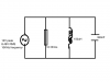
Link to Circuit diagram:
http://i695.photobucket.com/albums/vv313/patel5557600/kjadsbcksjdb_zps4027ce59.png
II have also attached a simple circuit diagram in this thread
My workings so far:
V=12V peak= 12/√2=8.49 V_RMS
f=10KHz
R=10Ω
L=150μH
C=330nF
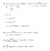
1 - Circuit Current
I_R=V/R=8.49/10=0.849A
I_L=V/X_L =8.49/9.42=0.901A
I_C=V/X_L =8.49/48.23=0.176A
I= √(〖I_R〗^2+(I_L - I_C )^2 )
I= √(〖0.849〗^2+(0.901-0.176)^2 )
I= 1.116A
2 - Phase Angle
〖G=〗〖1/R〗
〖G=〗〖1/10〗
〖G=〗〖0.1 s〗
〖θ=tan〗^(-1)〖G/Y〗
〖θ=tan〗^(-1)〖0.1/0.132〗
θ=〖37.15〗
3 - Impedance Using J operator
1/Z=√((1/R)^2+(1/X_L -1/X_C )^2 )
1/Z=√((1/j10)^2+(1/(-j9.42)-1/j48.23)^2 )
1/Z=√(((1∠0)/(10∠90))^2+((1∠0)/(9.42∠-9... )
Y=1/Z=√((0.1∠-90)^2+((0.106∠-90)-(0.020... )
Y=1/Z=√((0.1∠-90)^2+((0.106∠-90)-(0.020... )
4 - Power Dissipated
P=VIcosϑ
P=(8.49)(1.116)cos(37.15)
P=7.56W
Can someone please confirm these results? If I have gone wrong, could someone please correct me. Any help would be much appreciated.
Thank you
1) Total Circuit current
2) phase angle relative to the supply
3) Total Circuit Impedance using j operation (complex notation)
4) Power dissipated in the resistor
Link to Circuit diagram:
http://i695.photobucket.com/albums/vv313/patel5557600/kjadsbcksjdb_zps4027ce59.png
II have also attached a simple circuit diagram in this thread
My workings so far:
V=12V peak= 12/√2=8.49 V_RMS
f=10KHz
R=10Ω
L=150μH
C=330nF
1 - Circuit Current
I_R=V/R=8.49/10=0.849A
I_L=V/X_L =8.49/9.42=0.901A
I_C=V/X_L =8.49/48.23=0.176A
I= √(〖I_R〗^2+(I_L - I_C )^2 )
I= √(〖0.849〗^2+(0.901-0.176)^2 )
I= 1.116A
2 - Phase Angle
〖G=〗〖1/R〗
〖G=〗〖1/10〗
〖G=〗〖0.1 s〗
〖θ=tan〗^(-1)〖G/Y〗
〖θ=tan〗^(-1)〖0.1/0.132〗
θ=〖37.15〗
3 - Impedance Using J operator
1/Z=√((1/R)^2+(1/X_L -1/X_C )^2 )
1/Z=√((1/j10)^2+(1/(-j9.42)-1/j48.23)^2 )
1/Z=√(((1∠0)/(10∠90))^2+((1∠0)/(9.42∠-9... )
Y=1/Z=√((0.1∠-90)^2+((0.106∠-90)-(0.020... )
Y=1/Z=√((0.1∠-90)^2+((0.106∠-90)-(0.020... )
4 - Power Dissipated
P=VIcosϑ
P=(8.49)(1.116)cos(37.15)
P=7.56W
Can someone please confirm these results? If I have gone wrong, could someone please correct me. Any help would be much appreciated.
Thank you