Maker Pro
Maker Pro

PCB Induction Charger

J22L

Jan 24, 2013
17
Joined
Jan 24, 2013
Messages
17
yup thats the one we told you it wouldnt work

Dave

Yes, but will this design work?

None of the measurements are exact and my actual design will include many more turns, but I just made the picture quickly to explain what I mean.
 

Attachments

  • CoilsDesign.png
    CoilsDesign.png
    27.1 KB · Views: 94

davenn

Moderator
Sep 5, 2009
14,262
Joined
Sep 5, 2009
Messages
14,262
I have a Wavetek Model 30 Function Generator (http://www.radiomuseum.org/r/wavetek_function_generator_30.html) to use for my alternating current. Do you think this produces enough to test my design? .......
Thanks for all the help.

ummm the link doesnt tell us how much signal level the generator produces and I
couldnt find any other info for it
does the unit have written on it what its output level is ?

I would suspect only a Volt or so maximum which wont really be enough to do what you require, you would have to amplify that signal

Dave
 

J22L

Jan 24, 2013
17
Joined
Jan 24, 2013
Messages
17
I will see if I can find more information on it.

Thanks.
 

(*steve*)

¡sǝpodᴉʇuɐ ǝɥʇ ɹɐǝɥd
Moderator
Jan 21, 2010
25,510
Joined
Jan 21, 2010
Messages
25,510
(This is in response to post #19)

Yes, your original circuit is completely wrong.

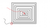
Notice how one coil (from the outside to the inside goes clockwise, and the other one goes anticlockwise.

Your best bet is to have one coil going from the outside to the inside on one side of the board, raking the ends (outside and inside) and applying power to them.

If you have double sided board, then you can place one coil on each side, and connect the centers together (through a hole in the board).

If you look at the way the current needs to flow, it will go round and round and round as it goes from one edge to the middle, then cross over and go round and round as it makes its way back to the edge. The thing is, the coils will be mirror images of each other. the current needs to be going around an imaginary axis through your board in the same direction. If it goes one way then the other, the effects cancel out.

In your diagram above, both coils go anticlockwise, but the current in one is the opposite direction to the other, So the current starts out going anticlockwise as it moves to the center, then goes clockwise on the way back out.
 

J22L

Jan 24, 2013
17
Joined
Jan 24, 2013
Messages
17
How can I make a design for just a one-sided PCB? Could you show me a sample design?

Thanks.
 

(*steve*)

¡sǝpodᴉʇuɐ ǝɥʇ ɹɐǝɥd
Moderator
Jan 21, 2010
25,510
Joined
Jan 21, 2010
Messages
25,510
The one in your post 21 is fine.
 

(*steve*)

¡sǝpodᴉʇuɐ ǝɥʇ ɹɐǝɥd
Moderator
Jan 21, 2010
25,510
Joined
Jan 21, 2010
Messages
25,510
Anything between several hundred and several thousand (if you're using 50Hz).

You still haven't answered my question about the signal source
 

J22L

Jan 24, 2013
17
Joined
Jan 24, 2013
Messages
17
The device does not say anything about the signal source. I don't know if it helps, but it is powered by a 9V power supply.
 

davenn

Moderator
Sep 5, 2009
14,262
Joined
Sep 5, 2009
Messages
14,262
Anything between several hundred and several thousand (if you're using 50Hz).

You still haven't answered my question about the signal source

that was answered in post #18

a Wavetek Function Generator 30 but we dont know what its output is

Dave
 

(*steve*)

¡sǝpodᴉʇuɐ ǝɥʇ ɹɐǝɥd
Moderator
Jan 21, 2010
25,510
Joined
Jan 21, 2010
Messages
25,510
If it's just a function generator, he might be able to get enough power to light a LED I guess.
 

J22L

Jan 24, 2013
17
Joined
Jan 24, 2013
Messages
17
I am not actually using my boards to charge anything, I just want to input a signal and put my other board on top of it attached to a voltmeter and see some numbers to show that they are transmitting power. So will the Wavetek work for my purpose?
 

BobK

Jan 5, 2010
7,682
Joined
Jan 5, 2010
Messages
7,682
Well, if you put a 50Hz signal into the inductor you are talking about, it will pretty much look like a short circuit, so I'm not sure what the signal generator will do with that. You should use the highest frequency the generator can produce, then there is a chance it will develop some voltage.

Bob
 

BobK

Jan 5, 2010
7,682
Joined
Jan 5, 2010
Messages
7,682
Okay, I did some calculating for you:

It looks to me like your board is abouut 50cm square with the traces being about 1mm spaced about 1mm with 12 turns in the spiral. This caluclates out (thanks Harald) to a whopping 3.5uH.

At 50Hz this has an impedance of 0.001 Ohms.

At 200KHz (the highest your signal gen goes) it is 4.4 Ohms.

Your signal generator is not likely to drive much power into even the 4.4 Ohm load.

I also calculate a 4 in square boad with 0.01 in traces 0.01 in appart for 100 turns. This comes out to a more reasonable 400uH. There you might be able to get something with it presenting a reasonable load of 50 Ohms at 20KHz.

Bob
 

J22L

Jan 24, 2013
17
Joined
Jan 24, 2013
Messages
17
Hi, thank you for your calculations. I am getting started designing a board that meets those specifications. Do you think you could tell me the formulas you used to calculate everything?

Thank you.
 
Top