Sir FrenchConnection67 . . . . . en France . . . . .( Bone Jower Mon -sewer . . . . .and thats with heeeeeeeveeeeeey implied emphasis on the sewer aspect)
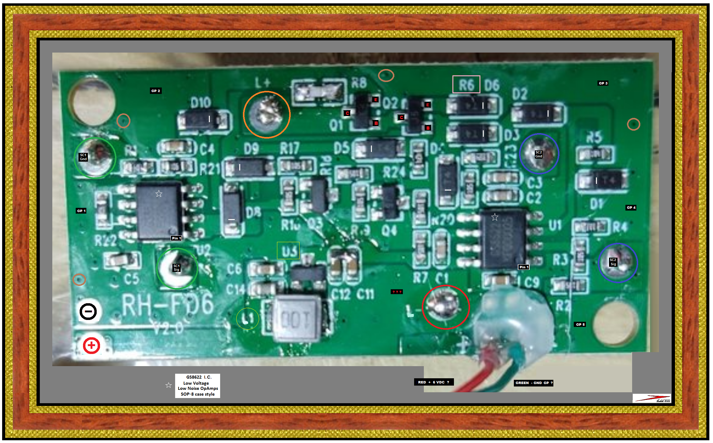
I've dodged the shadows / shadings / and light reflections and magged up definition, to the onset of pixelation threshold, so I now need your OHMMETER and learned / eagle like eyes upon the board for confirmations . . . . or . . .that's not so's.
MARK UP . . . . .
Moderators, kinde Sires, do not fully host this image yet, as I may need to make corrections . . . . dependent upon
Frenchies feedback . . . .I am using this off site hosting in the interim.
https://i.ibb.co/qg7gBDb/Walking-Sticks-Driver-Board.png
RED AND GREEN LEAD INPUT WIRE CONNECTIONS . . . . . .TESTING
Have no battery cells installed . . .for a non power applied test.
Initially . . . .
Take OHMMETER and put in its lowest OHMS range and short test leads together to confirm what meter reading is showing with a dead short.
Hopefully that is being a blob of vinyl / hot glue surrounding the connections,that pops off . . . . . or readings / connections can be made from the bottom.
OHM out from GREEN wire to
Ground Plane 5 markup . . . .with TEST PROBE TIP PIERCING . . . of the insulative GREEN resist.
IS IT BERING DEAD SHORTED ? . . . GOOD !
Then move on to my other differently marked
Ground Plane's . . . all the way back to
Ground Plane 1, origin.
On the way, also stop at top BLUE circle to confirm that it is that being that sense coils ground connection.
In the testing course, also stop at top left GREEN circle, to confirm that it is being that coils ground connection.
Next, move the OHMS meter probes to read the coils wire resistance between those GREEN and BLUE sensor coils.
M . . a . .a . .a . .a . .a . .a . .a . .n . .y turns of berry-berry fine wires-us-us-es . . . .are being used . . . . .Pass that ohms info back.
Now we have the large central "stick-kicker" impulse electromagnet connections, as being the RED and ORANGE circles.
Read that coils ohmmage and be expecting it as a quantum downward jump.. . . . . . . . . Pass that ohms info back.
Move OHMS testing down to the RED circle coil connection near the RED power wire and see if dead a short connection is present between RED power input wire and the RED circle L minus connection . . . . .expecting same.
Holding one OHMS connection on that L minus connection, take the other OHMS probe and PIERCE thru the green resist at my three
RED ??? markings and confirm that specific GREEN ISLAND is connected to, and should be your +6 VDC supply to its other connections being made into it.
Remember that OHMMAGE reading, being previously found between RED and ORANGE circles, lets now test once again, put one of your OHMS meter probes at RED circle and the other probe moves down to Transistor Q1 Collector, to see if that same resistance value was now being read again. If not being the same reading . . . is it possibly reading an OPEN circuit ?.
Transistors Q1 and and Q2 pulse drive that L coil " stick driver" solenoid.
The overall soldering integrity on L+ coil ORANGE circle connection looks like
SCHEISS.
Undoubtedly, a neophytes attempt at drip / drop / splattering on, of a soldering joint.
Adddditionally . . . . and thats being heavvvvy on the addddddd's . . . . as per the top R8 . . .I'm expecting to be a looooow ohmmage emitter resistor to ground. By virtue of using such a low 6VDC supply level.
Looks like it has the same sloppy solder install treatment and is being upside down, white side up, black, marked up side being downwards.
TESTING FROM MARKUPS . . . . .
Top left corner quadrant . . . . are found two diagonally oriented GREEN circles for making the connections into the units magnetic sensor coils.
Top left, I think will be the grounded terminal, and with the bottom right terminal being the induced signal out.
Central right on the board, will be the the other directions like sensor coil with my hesitant 50% degree of uncertainity, in its top BLUE circled connection being its grounded connection and its bottom right BLUE, being its signal output.
INCIDENTALS . . . .
Confirm all of my cathode / bar markings on the ends of all of those T4 surface mount power diodes . . . .( 1N4007 wannabes ). . . are now marked properly . . . . . .Hi Diddley Dee . . . . . . know what ? . . .diode Deee7 . . . . .I never did not see ?
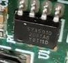
No data sheet pin outs were found on the STAR marked GS8622 op amps, since no data sheet was ever found.
WORKAROUND . . .
Look at my PALE BLUE divisional line . . . . . expect there being one power connection, two inputs and one output on each half.
Pull out ye olde OHMMETER again and one lead goes to a
Ground Plane connection and the other test lead probes all 8 I.C. pins for a direct connection. The now found pin is the power minus for the I.C.
Move one OHMMETER probe to RED L- coil connection and use other meter probe to find the pin that direct connects to it. That pin will be the I.C. power connection.
Now lets see if we get lucky, One OHMMETER probe goes to the SC1 GREEN coil connection and the other OHMS probe seeks all other 6 connections
( since the 2 powers connections are already found). I perceive,pins 1-4, due to their closest proximity to GREEN SC1 terminal .
With your success, we will then eventually know that I.C.'s . . . .heretofore unknown . . . two power connections and its one active input pin being used.
My forthcoming, powered up, test procedure will then let us then detect, which is being the I.C.'s amplified signal output pin.
CONFIRMATIONS . . . . .
Go back and reread to be sure ALL info requested is being passed forward after your testing and making reply in the forthcoming post from you.
In the interim, I am prepping a write up on that "bastard" PCB that is installed . . .series . . .inline with your battery . .6VDC supply . . .and this MAIN board that we are now evaluating.
ALSO . . . ALSO . . .
ALSO . . . give the number / lettering of the 8 pin . . . U1 I.C. . . . . on this new board, just being mentioned.
FUTURE TESTING MATERIEL NEEDS . . . . .
A 1000 ohm resistor of a 100 . . . . . .or . . .
CONSIDERABLY LESS ! . . . .wattage rating . . . . . ( jes' messin' wit cher' mind ! )
YOUR FINAL POST . . . .
You have the " Eiffel Tower " already built up, and in YOUR hands . . . . . why degrade to that posters pile of hot hog hocky and its technique . . . .
we just have to techno analyze yours and repair it.
73's de Edd . . . . .
Ambition . . . . . is a poor excuse for not having sense enough to be lazy.
.
 Screenshot_2022-05-19-15-31-02-184_com.miui.gallery.jpg127 KB · Views: 30
 Screenshot_2022-05-19-15-32-15-776_com.miui.gallery.jpg130 KB · Views: 25
 Screenshot_2022-05-19-15-32-22-238_com.miui.gallery.jpg94.3 KB · Views: 24
 Screenshot_2022-05-19-15-32-28-726_com.miui.gallery.jpg107.7 KB · Views: 20
 Screenshot_2022-05-19-15-32-34-831_com.miui.gallery.jpg95.4 KB · Views: 25
 . But hey, ho....might be what I was asking for when you adventure yourself outside of your confort zone on forums). My only testing equiment is a multimeter. I dont have an oscilloscope I am afraid as I dont need it in my day to day job. I have great understanding of fault finding as I have repaired automatic doors for the last twenty years though so I am not a complete newbie neither. Just missing out on the electronic side of it.