


Raven Luni
- Oct 15, 2011
- 798
- Joined
- Oct 15, 2011
- Messages
- 798
Raven Luni submitted a new Showcase Item:
PIC Programmer Made From USB Keyboard
Read more about this showcase item here...
PIC Programmer Made From USB Keyboard
Following on from this thread in the microcontrollers section, I've started my actual build. The keyboard was a cheap £6 one from the supermarket.
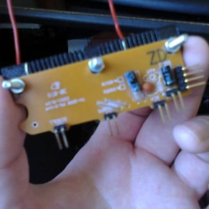
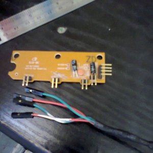
I've replaced the LEDs with header pins and done the same for the external connector (the wires were just soldered to the bottom with a pathetic blob of hot glue to hold it together). There were also a couple of unused holes for an extra bypass capacitor - a handy place to put another couple of pins for the voltage rails.
Contrary to the initial concept diagram, these LEDs are connected common anode, so some redesign will be needed.
Quick test with some LEDs:
And this is the revised schematic:
LED assignments:
D1 (Scroll Lock): Clock
D2 (Caps Lock): Data
D3 (Num Lock): Verify Mode
When the LEDs (D1 - D3) are on, the bases of the respective PNP transistors (Q1 - Q3) are pulled down, turning them on.
When D3 is off, the system is in data entry mode and the base of NPN transistor Q4 is held high via the 10K pullup resistor, allowing the data state (D2) to control pin 13 (RB7) of the PIC.
When D3 is on, the system is in verify mode, Q4 is turned off, and Q3 is turned on, allowing the data from pin 13 to switch Q5, which in turn switches Q6. Q6 bridges the column and row connections for a given key and the key state is read by the controller program.
First hurdle: Doing a simple test of the transistor logic I discovered that D2 and D3 were misbehaving (D1 - D3 have been moved and are driven by their relevant transistor outputs).
To the best of my reasoning, I'd say that the base-emitter voltage at Q4 is pulling down the base of Q3. I'm guessing this is probably a common pitfall that the more experienced are aware of. For everyone else - there you go - dont make this mistake.
Here is the updated schematic. This logic works.
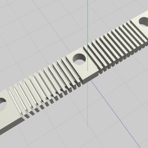
The joys of 3d printing - I made this attachment for the matrix contacts. It's wired for the Q key (to use as an output).
Success - after alot of trial and error and things not working the way the datasheet says (see associated rant). Using a test program I was able to write to both the program and data memory and correctly read...
Read more about this showcase item here...