Maker Pro
Maker Pro

Please help a newbie connect woofer

Gediminas

Nov 24, 2015
22
Joined
Nov 24, 2015
Messages
22
Hello!
To begin with, a little background: I am absolutely new in electronic and anything related to it, but recently rewired old speakers I found in my fathers attic, really liked the process (probably found a new hobby) and decided to make my own sub-woofer box as my first project. Bought a speaker, surfed internet a bit and find box plans, but decided to modify it a bit and add led lightening. Everything went pretty well, but now I encountered few questions and don't seem to find an answer on web, everything is confusing or not exactly I am looking for. Please give me some advice.

1) I connected led strip (4 segments x3 leds) to woofer and tested it, but it seem to light up only when volume is turned very loud, I would like it to shine in all volume range. Is any way to amplify signal to led strip?
2) I did not think through how I am going to connect woofer to my amplifier. Can you suggest clever way to do it?
3) In the test run (directly connected woofer instead of one speaker) woofer seemed way more quieter than I expected. Is there some way to make it play louder or it is because my amplifier and woofer limitations?

My amplifier Marantz PM583

Power output: 40 watts per channel into 8Ω (stereo)
Frequency response: 10Hz to 50kHz
Total harmonic distortion: 0.05%
Damping factor: 50
Input sensitivity: 4.5mV (MM), 400mV (line)
Signal to noise ratio: 75dB (MM), 90dB (line)
Channel separation: 60dB (line)

Woofer I bought Blow A-200
8'' Woofer
Max. Input power: 300W
Impedance: 8 Ohm
Frequency Response: 42Hz-6KHz
Sensitivity: 91dB/1w/1m
Magnet weight: 30 OZ
Aliuminium Voice Coil: 1.5''

I am adding few diagrams of my project:

My box plans
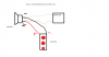
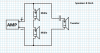
Instruction how to connect woofer I found (won't it burn my amplifier?)
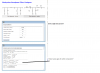
I found led wiring diagram, it uses battery, would it make led shine during lover volumes? (diagram source http://www.instructables.com/id/Music-LED-Light-Box/step6/Building-the-circuit/)
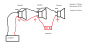
How I connected leds and woofer
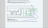
My working speakers connection diagram (maybe there are some clever way to connect woofer inside it?)
My amplifier back

Any help appreciated. Thank You in advance, and sorry for my (probably) dumb questions.
 

Attachments

  • Box plans cut.png
    Box plans cut.png
    203.1 KB · Views: 231
  • connecting.jpg
    connecting.jpg
    31.2 KB · Views: 417
  • led.gif
    led.gif
    7.7 KB · Views: 160
  • pajungti led.png
    pajungti led.png
    9.8 KB · Views: 246
  • kolonele sujungta.png
    kolonele sujungta.png
    16.4 KB · Views: 211
  • stiprintuvas.jpg
    stiprintuvas.jpg
    96.1 KB · Views: 237

dorke

Jun 20, 2015
2,342
Joined
Jun 20, 2015
Messages
2,342
Welcome to EP.
You are talking about a Sub-Woofer but the speaker you purchased is not really suitable for that purpose mainly because of it's 42Hz lower bandwidth-it should be lower.

* The way you connected 2 woofers in parallel is creating an overload condition to your AMP it can't support 4 ohm loads.
sub-woofer1.png

* Why would you connect a tweeter in a sub-woofer box?

* In this connection you again overload your AMP output by connecting a 4 ohm load

connecting.jpg

* Sub-woofers have their dedicated output ,which your AMP lacks.

* The issue of the LEDs is a minor,relatively easy one.
You do need to address the above issues before it.

* Have you considered a Ported Box design?
 

Gediminas

Nov 24, 2015
22
Joined
Nov 24, 2015
Messages
22
Thank you for your answer. I'm sorry, maybe I did not explained correctly. Diagram with two speakers and tweeter is from my other, working speakers, which are connected to AMP. Now I builded (only paint left) ported subwoofer box with one woofer and I want to connect everything somehow.
I put other speakers diagram, because, I think, compensating for the lack of dedicated woofer output, I somehow could connect woofer to that speaker box. As I imagine connect that box directly to AMP and woofer box, I build, to that speaker box.
That is my uneducated idea. I don't know if its good one, so I'm looking for someone with more experienced opinion.
And about that connection in my diagram. Is it done incorrectly? About 3 years ago when I found that box in my fathers attic I brought it to the guy who declared himself as expert, he changed speaker and connected this way... Should I rewire it? Because I don't know why but my AMP worked fine for all this time.
 

Gryd3

Jun 25, 2014
4,098
Joined
Jun 25, 2014
Messages
4,098
There are self proclaimed experts for everything.
The fact is that an AMP is designed to drive a specific load. You can alter this load, but the amp will not run as expected... It has two alternatives to working happily.
Connecting a Load that is too small will cause the output current to increase which will cause an increase in waste heat generated internally which could cause a failure.
Connecting a Load that is too large will restrict the output requiring you to turn the unit up more to compensate...
You get your ideal output when the source and load are matched. This is what dorke is talking about.
Your AMP may be working fine, but it's not operating as intended. Ultimately it's your call how you want to treat it.
 

Gediminas

Nov 24, 2015
22
Joined
Nov 24, 2015
Messages
22
Thanks again for answers. I tried to design a fix for this problem (3 speakers diagram) and also tried to incorporate my sub woofer and lights somehow (4 speakers diaram) into one of the speakers circut. For lights I used diagram I found on google. Please take a look and tell me how to fix it if its wrong. All the speakers are 8 Omh. Part in the red square going to be in the other, sub woofer box.

Also, could You explain battery part, is it correct? Should it be inverted?
And for the conductor near tweeter, I have no idea how big it should be I'm planning to use the same one I found then first opened the speakers box.
 

Attachments

  • mano kolonele.png
    mano kolonele.png
    32.6 KB · Views: 205
  • mano shema woofer.png
    mano shema woofer.png
    513.2 KB · Views: 274

dorke

Jun 20, 2015
2,342
Joined
Jun 20, 2015
Messages
2,342
The left photo is fine ,
the other one has a problem:
It is not good to connect the tweeter with the mid in series.
It is better to omit the mid in series with the tweeter.

What are the LEDs you are using?
and what is the transistor?
You can have the left arm of the 1K resistor at the + of the AMP,
for larger sensitivity.
 

Gryd3

Jun 25, 2014
4,098
Joined
Jun 25, 2014
Messages
4,098
I think you should build a cross-over instead of wiring a Mid and Sub in series, and a Mid and Tweeter in series...

It would come in 3 parts, and you can find diagrams everywhere. It's an ideal solution.
Essentially, you build a :
- 'low-pass' filter and attach it to the sub.
- 'High-pass' filter and attach to the tweeter.
- 'Band-pass' filter and attach it to the mid(s).
The inputs for all filter can be tied together.
*A band-pass filter can be build by daisy chaining a low-pass and high-pass together... The goal here is to block low notes, and block high notes...

Anyway, This would let you use an 8Ω Sub, Mid and Tweeter.

*Key components and how they work!
- Inductors, These block high frequencies. A higher Henry rating will let higher frequencies pass through.
- Capacitors, There block low frequencies. A lower Farad rating will let lower frequencies pass through.

You will find many different example online called 'orders' ... first order, second order... etc.
The higher orders block the frequencies more aggressively, but are more complex to build. The lower orders gradually cut the frequency from the speaker and can be built with a single capacitor for a highpass (which you have done), a single inductor for a lowpass, and one of each for a bandpass.

What do you think @dorke ?
 

dorke

Jun 20, 2015
2,342
Joined
Jun 20, 2015
Messages
2,342
@Gryd3 ,you are describing the correct way to build a multi-way speaker box.
However, I think the sub-woofer needs to be the only element in it's own box.
And worst than that, the main problem is the lack of a dedicated sub output from the AMP.
so this "sub-woofer project" is doomed from the start...:(
 
Last edited:

Gryd3

Jun 25, 2014
4,098
Joined
Jun 25, 2014
Messages
4,098
@Gryd3 ,you are describing the correct way to build a mult-way speaker box.
However, I think the sub-woofer needs to be the only element in it's own box.
And worst than that, the main problem is the lack of a dedicated sub output from the AMP.
so this "sub-woofer project" is doomed from the start...:(
I missed the fact that they are all in the same box... that poor mid and tweeter are going to be pounded by the pressure created by the sub...
Although I would not put the project out of it's misery due to a lack of a dedicated sub-output... although I'm curious what frequencies get passed out of the outputs... a sub may hardly do anything. (I'd try it with a proper box, but would not expect 'pounding bass'... maybe only some more clarity.)
 

Gediminas

Nov 24, 2015
22
Joined
Nov 24, 2015
Messages
22
Thank You for suggestions. I started thinking about new amplifier, but that will be in near (I hope) future. For now, I am not going to put sub-woofer in the same box, everything that I put into red square in my diagram is going to be in dedicated sub-woofer box I build. The only trick is that due lack of sub output on my amplifier I want to connect sub-woofer not directly to amplifier, but through one of my speakers (right or left). I realize that it going to sound little bit weird, but if it works I'll build another similar box to other side or save enough money for new amplifier. Either way I found it perfect learning opportunity and quite interesting hobby.
What do You guys think? Would it work?
 

Gryd3

Jun 25, 2014
4,098
Joined
Jun 25, 2014
Messages
4,098
Thank You for suggestions. I started thinking about new amplifier, but that will be in near (I hope) future. For now, I am not going to put sub-woofer in the same box, everything that I put into red square in my diagram is going to be in dedicated sub-woofer box I build. The only trick is that due lack of sub output on my amplifier I want to connect sub-woofer not directly to amplifier, but through one of my speakers (right or left). I realize that it going to sound little bit weird, but if it works I'll build another similar box to other side or save enough money for new amplifier. Either way I found it perfect learning opportunity and quite interesting hobby.
What do You guys think? Would it work?
Partially...
You need to make sure the load being provided is correct.
You will benefit a great deal from using a cross-over.
Most dedicated sub outputs are merely a mono-channel output that is passed through a low-pass filter anyway. They often have dedicated controls.
You will find the lower sounds will be audible and clearer, and same with higher sounds, but it will not 'thump' like someone would normally expect a sub-woofer to sound.
 

Gediminas

Nov 24, 2015
22
Joined
Nov 24, 2015
Messages
22
Please take a look at schematic I found and tired redesign (added led part) for my project.

On diagram I found sub-woofer and two mids were 8 Ohms, but tweeter only 6 Ohms, I left values unchanged for now, but how can I recalculate it? As far as I understand, I should change values of C6, C7, C8, R6, R7 and L7, right?

P.S all the parts inside red square will go into dedicated sub-woofer box.
 

Attachments

  • shema crossover forumui.png
    shema crossover forumui.png
    290.9 KB · Views: 299

Gryd3

Jun 25, 2014
4,098
Joined
Jun 25, 2014
Messages
4,098
Please take a look at schematic I found and tired redesign (added led part) for my project.

On diagram I found sub-woofer and two mids were 8 Ohms, but tweeter only 6 Ohms, I left values unchanged for now, but how can I recalculate it? As far as I understand, I should change values of C6, C7, C8, R6, R7 and L7, right?

P.S all the parts inside red square will go into dedicated sub-woofer box.
I'll say it's a good start, but would also mention that one being a little over the top.
You can make a decent crossover with far fewer components.

I would suggest looking at RC and RL filters. Two simple components can filter a speaker. The addition of more would be suggested for finer tuning.
Do you know what frequencies each speaker in your example is tuned to?
 

Gediminas

Nov 24, 2015
22
Joined
Nov 24, 2015
Messages
22
Thanks for the advice, I'll look for some info about RC and RL filters, maybe I'll manage to come up with something better, or at least it will be educational.

As for this schematic, yes, I found quite a bit info about it. OP was kind enough to put diagrams (I am adding it here). He used:
10" Scan speak 26w-8534g00 8-ohms sub-wooofer
Lower midrange an 7" Visaton AL170 8ohms
Upper midrange a 5" Visaton AL130 8ohms
And the tweeter a Seas H1499-06 27TBCD/GB-DXT 6ohm with bult in diffraction waveguide and rear chamber.

So how can I recalculate values? Should I use some program (the one I used to draw my version of diagram probably can do it, but I yet don't quiet get it fully how to do it) or there are some easier way?
Also at this moment this schematic way to complicated for me to count- how much load my amp will get from it? It should be 8 Omh, right?
 

Attachments

  • dažniai.JPG
    dažniai.JPG
    73 KB · Views: 205

Gryd3

Jun 25, 2014
4,098
Joined
Jun 25, 2014
Messages
4,098
Thanks for the advice, I'll look for some info about RC and RL filters, maybe I'll manage to come up with something better, or at least it will be educational.

As for this schematic, yes, I found quite a bit info about it. OP was kind enough to put diagrams (I am adding it here). He used:
10" Scan speak 26w-8534g00 8-ohms sub-wooofer
Lower midrange an 7" Visaton AL170 8ohms
Upper midrange a 5" Visaton AL130 8ohms
And the tweeter a Seas H1499-06 27TBCD/GB-DXT 6ohm with bult in diffraction waveguide and rear chamber.

So how can I recalculate values? Should I use some program (the one I used to draw my version of diagram probably can do it, but I yet don't quiet get it fully how to do it) or there are some easier way?
Also at this moment this schematic way to complicated for me to count- how much load my amp will get from it? It should be 8 Omh, right?
Well, the idea behind a cross-over is to split the output frequency range...
So in simple terms, if anything higher than 80Hz gets blocked by the mids and tweeter, then those sections can be looked at like an open circuit, no current should flow. The sub will get all the juice for anything lower than 80Hz... and the sub is 8Ω right?
In practice though , it's slightly more complicated. The actual rating will be slightly higher in this instance.

The problem arises from overlap... if you let 80Hz and below hit the sub, and 60Hz and above hit the mid... then for a range between 60Hz and 80Hz, the sub and mid will be in parallel and it will be like a 4Ω load was connected. Make sense?

Anyway, for calculating the cutoff, there are calculators EVERYWHERE on the internet if you do a quick search for the RC and RL filters I mentioned ;)

- RL - Low Pass
- RC - High Pass
(Combine the two types for a bandpass)
 

Gediminas

Nov 24, 2015
22
Joined
Nov 24, 2015
Messages
22
Thank you for simple explanation, internet is full of info, but its hard to get the needed one if I don't know what to look for, You made it hundred percent easier.

Yes the sub is 8Ω, all my speakers is 8Ω actually, I thought it should be like that, but now I understand it could be a good idea to combine different ones I'll do it next time...

I read about RL and RC and remade my diagram (did not put values yet, since I am looking for the design that would fit). It is little more simple and with less components. Is it any good?
Also I encounter problem that my both mids are the same, so since my amplifier can work between 8-16Ω load maybe it would be good idea to connect them in series (adding diagram)? If I understand correctly only drawback that speakers sound not as powerful, as it would be with 8Ω load? Or maybe it would be good idea to overlap that kind of connection with tweeter, so amplifier load would be back at around 8Ω load right?

Oh, and please tell me if I understood correctly: orders it like RC or RL filter count? More filters I connect one after another the bigger order of the last filter will be? And by doing that I get better and better sound filtering capability and clearer sound, right?supaprastinta 4way schema.png mano shema be reiksmiu.png
 

Gryd3

Jun 25, 2014
4,098
Joined
Jun 25, 2014
Messages
4,098
Your making great progress!
However, there is a big difference in behaviour that you should be aware of for the different kinds of filters.
Take a look at your Sub.
It's using an 'RC Low-Pass' filter... but take a sec to understand 'how' it works and you might want to swap it out for an 'RL-Low Pass'.

A resistor is a simple device and for sake of this discussion it does not have reactance.
A capacitor is a dynamic device, and for the same of this discussion will be looked at like a resistor:
- When a high frequency encounters a capacitor, it's the same as using a low value resistor.
- When a low frequency is encountered, it's the same as using a high value resistor.
An inductor is a dynamic device as well, and has the opposite behaviour as a capacitor:
- When a high frequency encounters an inductor, it's the same as using a high value resistor.
- When a low frequency is encountered, it's the same as using a low value resistor....

Soo... if you re-draw your Sub-Woofer section, you will find that the resistor lets in 'some' of the high frequencies, and the capacitor shorts it to ground... this particular filter only behaves as a Low-Pass because it shunts the high frequencies to ground.
If you replace the resistor with an Inductor, then the capacitor with a resistor then this change will keep the higher frequencies from entering completely which will let them hit the other portions of the circuit.

Does that help?

The rating of the capacitor or inductor defines what frequency they let through or block.
 

Gediminas

Nov 24, 2015
22
Joined
Nov 24, 2015
Messages
22
I can't stress You enough how great help You are and how grateful I am.

I can't get my hands on my speakers until tomorrow or day after tomorrow, so I don't know actual response frequency, but I tried to count theoretical values for all the components. For low pass and high pass filters I found simple calculator, but for band-pass it got little confusing. I'll adding screenshot of it, please help me understanding it. Or should I combine both filters from sub-woofer and tweeter to make a bandpass filter for mids and this use calculators I (hopefully) understood?
Also I keep thinking about total system impedance my amplifier going to get. Do I count it correctly?
 

Attachments

  • skaiciavimai.png
    skaiciavimai.png
    67.6 KB · Views: 149
  • schema su skaiciavimais.png
    schema su skaiciavimais.png
    817.8 KB · Views: 182

Gryd3

Jun 25, 2014
4,098
Joined
Jun 25, 2014
Messages
4,098
I can't stress You enough how great help You are and how grateful I am.

I can't get my hands on my speakers until tomorrow or day after tomorrow, so I don't know actual response frequency, but I tried to count theoretical values for all the components. For low pass and high pass filters I found simple calculator, but for band-pass it got little confusing. I'll adding screenshot of it, please help me understanding it. Or should I combine both filters from sub-woofer and tweeter to make a bandpass filter for mids and this use calculators I (hopefully) understood?
Also I keep thinking about total system impedance my amplifier going to get. Do I count it correctly?
Well, a 100Hz to 1.2kHz bandpass would be made by making a 100Hz high-pass, and a 1.2kHz low-pass . You daisy chain them together ;)
The sub, would use a 100Hz low-pass.

As far as the mid and tweater are concerned, there is a little overlap from 1kHz to 1.2kHz, so in that range, the impedance would be lower than expected. I'm sorry, but I cant accurately give you a result right now.
 

Gediminas

Nov 24, 2015
22
Joined
Nov 24, 2015
Messages
22
Thanks to You, I learned so much in few days and I feel that I'm getting closer to wiring part now.

I'm sorry, but I cant accurately give you a result right now.

No problem, You helped anyway. While it would be convenient for this moment to get results, but I would rather learn to count them myself. Problem is that either I don't know how to look for them or google doesn't offer any usable results on this topic. If You could recommend some literature about it it would be appreciated.

As far as I understood my total system impedance won't be constant (it'll change depending frequencies playing and speakers working at that moment, right?) and since my signal overlaying (I'm thinking about 120 Hz for sub-woofer, 90Hz-1100Hz mids and 1000Hz tweeter) is not that big so I shouldn't be worrying about it and leave it be, right?

I redesigned my diagram for more simple filters, for band pass I combined RL High pass and RL Low pass filters, or for High pass I should use RC filter like in tweeter?

Also getting back to question about using resistor to correct impedance for amplifier: is it legit way? Because now I counted my other speaker impedance I got it 5.333 Omh, I would like to raise it back to 8 Omh.

And last question for now: I trying to understand Chebyshev Bandpass filter and it calculation tool (not necessary I am going to use it now, but I still like to understand it), please tell me if my observations are correct.Chebyshev klausimas.png galutine.png
 
Top