skylar coy
- Apr 29, 2017
- 16
- Joined
- Apr 29, 2017
- Messages
- 16
This amp was built in the 70's and I need to replace the output transformer. Here is a schematic of the Amp. My issue is that I dont think the transformer is hooked up correctly now! Red is 16 ohm, Grey is 8 ohm, black is 4 ohm, brn is common. 8 ohm doesnt seem to be hooked up to anything. Just confused. Tell me what is wrong or if its just fine.
Amp pics: https://ibb.co/kU6NBQ
https://ibb.co/iP6NBQ
https://ibb.co/iKhJkk
Schematic: https://ibb.co/fWFXBQ
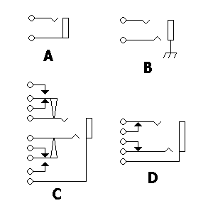
On the schematic is shows the 4 ohm and 8 ohm wires and two more un labeled with a little triangle in them then going to that like with the 2 black triangles on them. What are the triangles and what is the line?
Amp pics: https://ibb.co/kU6NBQ
https://ibb.co/iP6NBQ
https://ibb.co/iKhJkk
Schematic: https://ibb.co/fWFXBQ
On the schematic is shows the 4 ohm and 8 ohm wires and two more un labeled with a little triangle in them then going to that like with the 2 black triangles on them. What are the triangles and what is the line?
") basically my question why is the 8 ohm wire all by itself not connected to anything, why is com and 4 ohm connected to the output jack, and why is 16 ohm where it is in the pictures i put.
basically my question why is the 8 ohm wire all by itself not connected to anything, why is com and 4 ohm connected to the output jack, and why is 16 ohm where it is in the pictures i put.