Maker Pro
Maker Pro

Power drop

Poppapaul

Jun 24, 2021
9
Joined
Jun 24, 2021
Messages
9
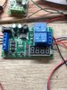
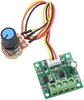
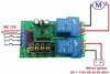
i have auto reverse module attached are speed controlers one each way all works great on a small 12 volt motot but will not run on my train layout I have 12 volts up until it gets to the motor checked voltage it's just 2 volts. Can anyone tell me why?
 

bertus

Moderator
Nov 8, 2019
3,321
Joined
Nov 8, 2019
Messages
3,321
Hello,

Do you have a schematic of your circuit?

Bertus
 

bertus

Moderator
Nov 8, 2019
3,321
Joined
Nov 8, 2019
Messages
3,321
Hello,

The boards do not tell me much about how they are connected.
Is one board a power regulator and the other the reverse switch?

Bertus
 

Poppapaul

Jun 24, 2021
9
Joined
Jun 24, 2021
Messages
9
The main board is the auto reverse unit which has two power supplies one for the unit and one for the motor.but I needed to regulate the speed so I attached speed controlers
 

bertus

Moderator
Nov 8, 2019
3,321
Joined
Nov 8, 2019
Messages
3,321
Hello,

It looks like you did not connect the speed regulator boards correctly.
Do you have details on both boards?
It looks like the speed regulator board has in and outputs.
The speed regulator board may not like being reversed.

Bertus
 

bertus

Moderator
Nov 8, 2019
3,321
Joined
Nov 8, 2019
Messages
3,321
Hello,

Have a look at the following bi-directional DC motor speed controller from quasar.

Bertus
 

Attachments

  • 3166_article.pdf
    983.7 KB · Views: 1
  • 3166v2.pdf
    192.5 KB · Views: 1

Poppapaul

Jun 24, 2021
9
Joined
Jun 24, 2021
Messages
9
Hello,

It looks like you did not connect the speed regulator boards correctly.
Do you have details on both boards?
It looks like the speed regulator board has in and outputs.
The speed regulator board may not like being reversed.

Bertus
 

Attachments

  • received_991290814948341.jpeg
    received_991290814948341.jpeg
    33.3 KB · Views: 3

Martaine2005

May 12, 2015
4,949
Joined
May 12, 2015
Messages
4,949
set + - ok are for the onboard timer I think.
Are you connecting power to the track?
As previously asked, show how it's all connected. Not pictures, a drawing. Unless the picture clearly shows all connections and where they go.

Martin
 

bertus

Moderator
Nov 8, 2019
3,321
Joined
Nov 8, 2019
Messages
3,321
Hello,

From the pictures, I can not tell wich connections are inputs and outputs on the speed controller board.
I would connect the speed controller board between the power source and reverse switch controller.

Bertus
 

Poppapaul

Jun 24, 2021
9
Joined
Jun 24, 2021
Messages
9
I'm trying to send you a picture of drawing but not possible at the moment.so I'll try to explain.from the auto reverse board working power is for the board on the left the other three are for manual push buttons which I don't want.to the right are four connections bottom two is 12 volt power the top two are connected to the speed controlers top one to one controller next one to the other controller.Then from each speed controler goes to each end of the motor and that's were I'm losing power it drops to two volts.I hope I've explained it ok..Thanks
 

Bluejets

Oct 5, 2014
6,920
Joined
Oct 5, 2014
Messages
6,920
Don't see that working at all...........as I see the connections in the photo

dodgy.jpg
 

Poppapaul

Jun 24, 2021
9
Joined
Jun 24, 2021
Messages
9
It works great with the little motor it will speed up and slow down but when I replace the motor to the track there's not enough power to drive the train.The voltage drops to 2 volts i need to try and maintain 12 volts
 

Poppapaul

Jun 24, 2021
9
Joined
Jun 24, 2021
Messages
9
The four buttons you asked about are program buttons so you can set how long it goes forward then delay then reverse
 
Top