Maker Pro
Maker Pro

Power Supply Failed - Samsung Plasma PS-42Q96HD

dailafing

Mar 2, 2014
4
Joined
Mar 2, 2014
Messages
4
There are so many posts online about how Samsungs were identified by the ticking or clicking relays, and everyone said it was almost always a bulging cap, or failing that it was a MOSFET...

Well, my Samsung has just joined the fun, but I was surprised to find that upon disassembly, everything looks fine to me...

No dry joints, or missing solder...
No bulging caps...
No scorching or burning
No cracked resistors or anything..

In fact, by my eye, visually everything is find save for some cobwebs and dust...

So I'd like to kindly refer to the experts here, and ask for a second opinion.
ideally I don't want to have to un solder everything and test it manually, because
1) its a pain, and
2) I don't really know what im doing.

I know how to be safe, and I've had my initiation when working on a live iMac pranging myself with 240v to earth via my chest
(Right hand earthed by holding metal LCD bezel, and left knuckle touching live 240v feed)

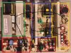
Please see video and pictures of my powerboard, (BN44-00162A, PSPF531801A, W2A)

Thanks

[img=http://s19.postimg.org/h0cbm220f/SCAN0155.jpg]
photo.jpg


[img=http://s19.postimg.org/625nhm2sv/photo.jpg]
SCAN0155.jpg


I did a 720p YouTube video passing over the circuts Here:
 

(*steve*)

¡sǝpodᴉʇuɐ ǝɥʇ ɹɐǝɥd
Moderator
Jan 21, 2010
25,510
Joined
Jan 21, 2010
Messages
25,510
The capacitors don't always bulge.

Give us a photo of the other side of the board and I'll point out the capacitors which would be most likely suspects.

If you have an ESR meter you could test them, but if you're willing, you could just replace them. It's reasonably cheap and easy.

The capacitors that are going to be the issue will be on the cold side of the board near heatsinks that have the rectifier diodes on them (often 3 terminal devices). The voltage ratings will be relatively low (10V to 35V) and there's normally more than one, so seeing several all lined up (and connected in parallel) is often another giveaway.
 

dailafing

Mar 2, 2014
4
Joined
Mar 2, 2014
Messages
4
Updating with front of the board

Thanks for your reply.

I just got off the phone to a chap who repairs these boards, and seemed very familiar with fixing Samsung's.

As soon as I said "but when I pulled the board out, the cap's weren't bulging at all"

he said

"Ah, its a plasma is it?"

He didnt want to say too much to protect his interests which was understandable.
It's as though he knew that since the caps weren't bulging, it must have been a plasma, and therefore may not be the caps at all?

Could anyone bring clarification to my concerns? thanks

Att: Front side pics...

image01.jpg


image02.jpg


image03.jpg


image04.jpg


image05.jpg


image06.jpg
 

(*steve*)

¡sǝpodᴉʇuɐ ǝɥʇ ɹɐǝɥd
Moderator
Jan 21, 2010
25,510
Joined
Jan 21, 2010
Messages
25,510
OK, it's not 100% certain, but here is my quick analysis of this power supply:

attachment.php


The black lines indicate a general flow of power through the power supply.

It starts in the lower left corner where the mains comes in and is filtered.

My conjecture is that the green box is part of a "green circuit" that acts to improve the power factor of the power supply essentially by acting as a boost supply to draw current from the mains through the full cycle, not just at the crests.

Then the orange box is the high voltage energy storage. I suggest these will be 400V capacitors.

From there you have the purple box which is actually two separate flyback supplies generating a number of rails. The orange part is the hot side (mains voltage)

Then the yellow box is the low voltage side of these regulators. The red circled capacitors are the ones most likely to fail.

Separately to all of this is a standby power supply which is the dark red box. The orange/black capacitor just below the black line I have drawn, and between the light and dark red boxes is probably the high voltage energy storage capacitor for this power supply. It is also likely to be a 400V capacitor. Within the dark red box I have circled the likely capacitors to fail.

Since you get nothing when you apply power, the first thing to check is the standby rail. You need to identify the output connector for this (I may not have done so correctly) and determine if this has the correct voltage.

Then move on to the other power supply rails.

Your images are large, but they're not clear enough for me to make out the writing on the board.
 

Attachments

  • PSU (Small).jpg
    PSU (Small).jpg
    79 KB · Views: 1,407

(*steve*)

¡sǝpodᴉʇuɐ ǝɥʇ ɹɐǝɥd
Moderator
Jan 21, 2010
25,510
Joined
Jan 21, 2010
Messages
25,510
The first thing to check is the fuse near the input connector :)
 

dailafing

Mar 2, 2014
4
Joined
Mar 2, 2014
Messages
4
The first thing to check is the fuse near the input connector :)

Hi Steve,

This is kinda helpful? Al least I'm talking to someone who clearly know what he's talking about!

I can take some pics focusing on the text you need to see if you like?

The fuses are all fine, and just to clarify, the unit attempts to start, there seems to be a 3 click cycle, varying in timing with no discernible pattern other than the last of the 3 clicks takes longer, and has the most variance in timing.

Is there a way I can test for the fault with my multi meter? (See pic)

Thanks for your help, it's really appreciated.

image.jpg
 

(*steve*)

¡sǝpodᴉʇuɐ ǝɥʇ ɹɐǝɥd
Moderator
Jan 21, 2010
25,510
Joined
Jan 21, 2010
Messages
25,510
Your multimeter can't measure what is required to test those capacitors.

Use it to measure the output voltages I suggested.

If you can tell me what is written on the capacitors I circled, and also the ones I pointed out as the high voltage energy storage caps that would be great.

A photo (or photos) so I can read the writing on the board in the yellow and dark red area would be great.
 

dailafing

Mar 2, 2014
4
Joined
Mar 2, 2014
Messages
4
image.jpg


Long story short...

I used my DMM in ohm mode to see if the components were connected to the board correctly.

I re soldered some dry connections. Specifically the VS & VA mosfets.

Put back in, works a dream....

Thanks for all help.
 

(*steve*)

¡sǝpodᴉʇuɐ ǝɥʇ ɹɐǝɥd
Moderator
Jan 21, 2010
25,510
Joined
Jan 21, 2010
Messages
25,510
Well done.

Incidentally, my suggestion to read the output voltages was to check that the voltages are in range. Failed caps tend to leave the voltage approximately correct. The fault you found would not.

The person who asked if you have a plasma must be aware of certain faults endemic to these units.

You probably saved yourself $200 :)
 
Top