Maker Pro
Maker Pro

Programming PIC to sontrol 6x SERVOs

camerart

Aug 18, 2010
126
Joined
Aug 18, 2010
Messages
126
You have a delay in the handler. This means you really don't understand how it is supposed to work, so let me try to explain it.

Bob

Hi B,
When you say I have a delay, do you mean this: 'WaitUs timxh ?
The apostrophe is when it is commented out. I realised my mistake.

Thanks, I'll try again tomorrow.
C.
 

BobK

Jan 5, 2010
7,682
Joined
Jan 5, 2010
Messages
7,682
Ah, okay. Like I said, I was not familiar with the language you are using.

Bob
 

camerart

Aug 18, 2010
126
Joined
Aug 18, 2010
Messages
126
Ah, okay. Like I said, I was not familiar with the language you are using.

Bob
Hi B,
How does this look so far?
I can see that there are some mistakes,and some lines for testing, that need removing.
If you can look at the INTERRUPT LOOP, and see if it looks something like your ideas.

I have a waitms 14, which will be calculated later as a TMR0 delay.

Should there be OFF delays as well, or should it work with only ON/DELAY/OFF?
C.
 

Attachments

  • 18LF4431 SERVO 250618 1100.txt
    10.6 KB · Views: 55

camerart

Aug 18, 2010
126
Joined
Aug 18, 2010
Messages
126
Hi B,
Thank you for your patience explaining how the TIMER works.
It is almost working, but needs Oshonsoft language skills to go farther.
Much appreciated,
Camerart
 
Last edited:

camerart

Aug 18, 2010
126
Joined
Aug 18, 2010
Messages
126
Hi,
Update!
I'm concentrating on other things at the moment, so this is a summary.
I have now got the SERVO ouputs to work, using PPM (I think) with a timer interrupt.
C
 

camerart

Aug 18, 2010
126
Joined
Aug 18, 2010
Messages
126

Attachments

  • AK8963C BREAK OUT BOARD.jpg
    AK8963C BREAK OUT BOARD.jpg
    186.2 KB · Views: 2
  • GEN NEO-M8N.jpg
    GEN NEO-M8N.jpg
    347.6 KB · Views: 1
Last edited:

Harald Kapp

Moderator
Moderator
Nov 17, 2011
13,057
Joined
Nov 17, 2011
Messages
13,057

camerart

Aug 18, 2010
126
Joined
Aug 18, 2010
Messages
126
Google is your friend:

"C" huh? What do you mean by this?
Hi H,
Thanks for your search, but neither of them is SPI. The first one is I2C and the second one requires the SPI wires as shown here:
Cheers, C for Camerart.
 

Attachments

  • NEO-8 SPI wires.jpg
    NEO-8 SPI wires.jpg
    227.7 KB · Views: 2

Harald Kapp

Moderator
Moderator
Nov 17, 2011
13,057
Joined
Nov 17, 2011
Messages
13,057
I'm sorry, an oversight on my part.
What is the reason you need SPI and can't use I²C or UART?
 

camerart

Aug 18, 2010
126
Joined
Aug 18, 2010
Messages
126
I'm sorry, an oversight on my part.
What is the reason you need SPI and can't use I²C or UART?
Hi H,
I chose SPI when I started this project a few years ago, so all of my peripherals use it.

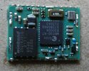
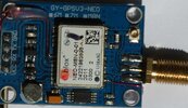
Regarding the GPS UART:
The UART shares it's use with Radio control and needed a switch between the 2x, so if I can get SPI to work, it would solve this.
The UART alternative, is to use a software UART, which while it works, the problem is that it grabs the PIC process.
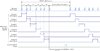
The SPI of the GPS is immensely difficult to do. If anyone knows how to do it let me know, but even if you search, beware there are rabbit holes that go nowhere.
C.
 

juliasmith

Nov 13, 2022
11
Joined
Nov 13, 2022
Messages
11
You can use picaxe as you are using PIC's for doing your project.But arduino would be much better than using PIC.
 

camerart

Aug 18, 2010
126
Joined
Aug 18, 2010
Messages
126
Did you look.,.?
Hi B and J,
No, my apologies.
I've been using PICs for a long time, so I didn't move to Arduino, when they got popular, as I had PIC CODE.
Instead of the Arduino libraries, that are simply used, I chose to write my own libraries, so I understood them
C
 
Last edited:
Top