Maker Pro
Maker Pro

PS900 Oscilloscope Sweep Function Not Working

oscilloscopeEnthusiast

Feb 12, 2022
11
Joined
Feb 12, 2022
Messages
11
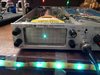
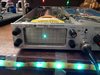
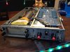
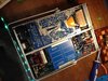
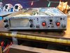
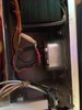
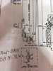
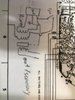
I have a PS900 Oscilloscope from about 1972 that doesn't have a working horizontal sweep. I have found a schematic and wiring diagram, but don't understand it fully. I think the issue is in the sweep generator circuit, probably where the frequency is generated. Everything else seems to work fine other than the CRT shutting off after a few seconds sometimes. If anyone understands this better than I do, please help.
Here is where I found the schematic and wiring diagram: https://bama.edebris.com/manuals/vudata/ps900/
If there is a link on PS900, it is not intended.
 

ramussons

Jun 10, 2014
463
Joined
Jun 10, 2014
Messages
463
Do you get a spot on the screen?
Is the vertical sweep active?

Make sure that you are not in the XY mode by mistake.
 

oscilloscopeEnthusiast

Feb 12, 2022
11
Joined
Feb 12, 2022
Messages
11
Yes, I get the spot on the screen (except when the CRT turns off) and the dot moves up or down when I apply a voltage through the probes. As for the XY mode, I am not sure what that is and if the oscilloscope has it, it is not clearly labelled. This is my first oscilloscope, and I don't know much about oscilloscopes.
 

ramussons

Jun 10, 2014
463
Joined
Jun 10, 2014
Messages
463
It is a dual channels oscilloscope and you should get 2 spots.

Give an input to both channels and see what happens.

And a photo of the oscilloscope front will help us a lot more.
 

oscilloscopeEnthusiast

Feb 12, 2022
11
Joined
Feb 12, 2022
Messages
11
To me, the oscilloscope does not seem like it has two inputs. There is only one input jack, and I have only one probe. The only other input thing is the trigger input. The probe I have has two parts, though I think one is for ground.
 

Attachments

  • IMG_0253 (640x480).jpg
    IMG_0253 (640x480).jpg
    180.3 KB · Views: 11
  • IMG_0247 (640x480).jpg
    IMG_0247 (640x480).jpg
    190.2 KB · Views: 11
  • IMG_0250 (640x480).jpg
    IMG_0250 (640x480).jpg
    80 KB · Views: 10
  • IMG_0251 (640x480).jpg
    IMG_0251 (640x480).jpg
    46.1 KB · Views: 10
  • IMG_0253 (800x600).jpg
    IMG_0253 (800x600).jpg
    238.4 KB · Views: 11
  • IMG_0247 (640x480).jpg
    IMG_0247 (640x480).jpg
    190.2 KB · Views: 9
  • IMG_0250 (640x480).jpg
    IMG_0250 (640x480).jpg
    80 KB · Views: 10
  • IMG_0251 (640x480).jpg
    IMG_0251 (640x480).jpg
    46.1 KB · Views: 9
  • IMG_0252 (640x480).jpg
    IMG_0252 (640x480).jpg
    192.2 KB · Views: 10

oscilloscopeEnthusiast

Feb 12, 2022
11
Joined
Feb 12, 2022
Messages
11
After looking into it more, I think the issue is probably in the trigger generator. While trying to test this though, a wire from the transformer shorted and made a loud pop. Luckily, nothing was damaged except for a small crater on the inside of the case. When I tested the output from the trigger generator, it stayed around 5 volts, occasionally jumping down to zero. I think this means that the integrating capacitors are usually held to zero volts by shorting.
 
Last edited:

kellys_eye

Jun 25, 2010
6,514
Joined
Jun 25, 2010
Messages
6,514
Set the front panel trigger switch to 'external' and the one below it to 'auto' and apply a pulse to the trig-input socket and see if the spot moves. If not then the horizontal deflection and/or timebase circuitry needs to be checked.

If the horizontal position control moves the spot left/right then it's down to the timebase section.
 

oscilloscopeEnthusiast

Feb 12, 2022
11
Joined
Feb 12, 2022
Messages
11
Do I just use the regular probe to do that? I don't have any other probes or things to connect to that. The horizontal position knob does work though. I also have done some work testing it based on the outputs of various circuits labeled in the schematic which I have a link to in the first post if needed. Based on my testing, which I could not do with an oscilloscope because I do not have another (I used a multimeter), I think the issue is in the trigger circuit. I am also still one to suggestions though.
 
Last edited:

oscilloscopeEnthusiast

Feb 12, 2022
11
Joined
Feb 12, 2022
Messages
11
I have found that the transformer is not wired how it is shown in the schematic, https://bama.edebris.com/manuals/vudata/ps900/
It is wired so that the switch is not used to disconnect the primary windings and only one of the primary winding is hooked to power. The switch still works to turn it on and off, but only after the transformer. I included images of about how things are connected and from the schematic of how it should be. Sorry about my schematic drawing, I am not very good. Hopefully good enough though. I am not sure if I should try to wire the transformer in the way shown in the schematic, so I am asking for help. Also, the wire to the switch from the power plug should have a fuse in it. The fuse is there, but the wire is not connected to the fuse.
 

Attachments

  • IMG_0064.JPG
    IMG_0064.JPG
    43.7 KB · Views: 4
  • IMG_0063.JPG
    IMG_0063.JPG
    14.2 KB · Views: 4
  • IMG_0061.JPG
    IMG_0061.JPG
    16 KB · Views: 4

oscilloscopeEnthusiast

Feb 12, 2022
11
Joined
Feb 12, 2022
Messages
11
I just tested the voltage from the -7.8 volt regulator and it is at about -7.88 volts. The documentation I found about the oscilloscope includes a description of initial testing that says the voltage for the regulator should be very close to -7.8 volts. I am not sure if this would have an effect on the functionality of the oscilloscope but I would like to know if I should adjust it or not. I also found that the FET is not getting power and is keeping the capacitors discharged. If needed, I linked the documentation for the oscilloscope in the first post.
 
Last edited:

Erstwhile

Apr 12, 2022
43
Joined
Apr 12, 2022
Messages
43
What other test equipment do you have available?
A signal generator? An audio generator? Pulse generator? Voltmeters? isolation transformer?
For instance, a low level sawtooth wave from a signal generator put into the Ext. jack could/should make the dot on the screen become a line. That would indicate the horizontal amps working. Have you tried to make it show a Lissajous pattern? A low level output from an audio oscillator could also let you know if horizontal amps are working.

[edit] I just looked at the schematic you linked to in your first post. Since it does have a couple of waveforms shown in the Horiz. section, it would be useful if you have access to another o-scope to trouble shoot this one. Just be careful to isolate the grounds.
 
Last edited:

oscilloscopeEnthusiast

Feb 12, 2022
11
Joined
Feb 12, 2022
Messages
11
I don't have much test equipment. All I think I have right now is a cheap multimeter. I also don't know much about electronics and waveforms as this is pretty much my first electronics type project, other than building some circuits I found online and some Arduino stuff. I think the horizontal amps are working because the horizontal position adjustment works, though I am not certain. If it would work, I could probably find an online waveform generator and use a headphone jack or use a 555 timer circuit I made. I don't currently have another oscilloscope, but I may be able to borrow one. If you could help me understand how the sweep and trigger circuits work, that might also help. Thank you!
 

Erstwhile

Apr 12, 2022
43
Joined
Apr 12, 2022
Messages
43
A cheap multimeter and then a "cheap" o-scope*. That is how I started out 40+ years ago!
And look at me now! (an electronics hoarder) B^)
I'll do some more thinking on this...

*a Bell and Howell branded version of a Heathkit oscope I bought used for $80
I admit, your o-scope will probably outperform the one I had.
 

oscilloscopeEnthusiast

Feb 12, 2022
11
Joined
Feb 12, 2022
Messages
11
Thanks! I think I will take your advice and get one. If you could help me understand the circuit or have any suggestions for oscilloscopes, that would also be useful.
 
Last edited:

kellys_eye

Jun 25, 2010
6,514
Joined
Jun 25, 2010
Messages
6,514
but I would like to know if I should adjust it or not.
No. It is well within tolerance. If it ain't bust, don't fix it.

You have power to the unit so don't mess with the wiring.

Have you read the documentation for the 'scope to determine how to set it up and use it? We have to know that there is an actual fault rather than simple 'user error' before we can go further else we're wasting our time.
 

kellys_eye

Jun 25, 2010
6,514
Joined
Jun 25, 2010
Messages
6,514
Check for 180V from the power supply section. This powers the horizontal deflection amplifier and seems to be the ONLY thing that isn't working (i.e. you have a spot and vertical movement - this indicates the other supply lines are all present else one or other wouldn't be happening).
 

Erstwhile

Apr 12, 2022
43
Joined
Apr 12, 2022
Messages
43
I was thinking of setting up a 555 timer chip as an astable oscillator to input into the Trigger In jack to see if that would cause it to scan...
 

Erstwhile

Apr 12, 2022
43
Joined
Apr 12, 2022
Messages
43
Oh, you mentioned having an Arduino, that could be set up to provide pulses like a pulse generator, to put into the Trigger In.
 
Top