
TechQuestion
- Jan 23, 2018
- 1
- Joined
- Jan 23, 2018
- Messages
- 1
Hello, I am building a PWM controlled power stage for a motor.
I have created a circuit in proteus and it works, kinda cool, but, I have the feeling it has to be inproved and some questions about Integrating the signal and how the transistor 2n3055 works. I would like somebody elses opinions and corrections.
The target is to regulate the voltage of a load via PWM duty and 2n3305 transistor.
Resources:
Proteus files : https://drive.google.com/drive/folders/1EYbGP7WJoEnfO8Z9XC5a5SSe4Bv2Sw18?usp=sharing
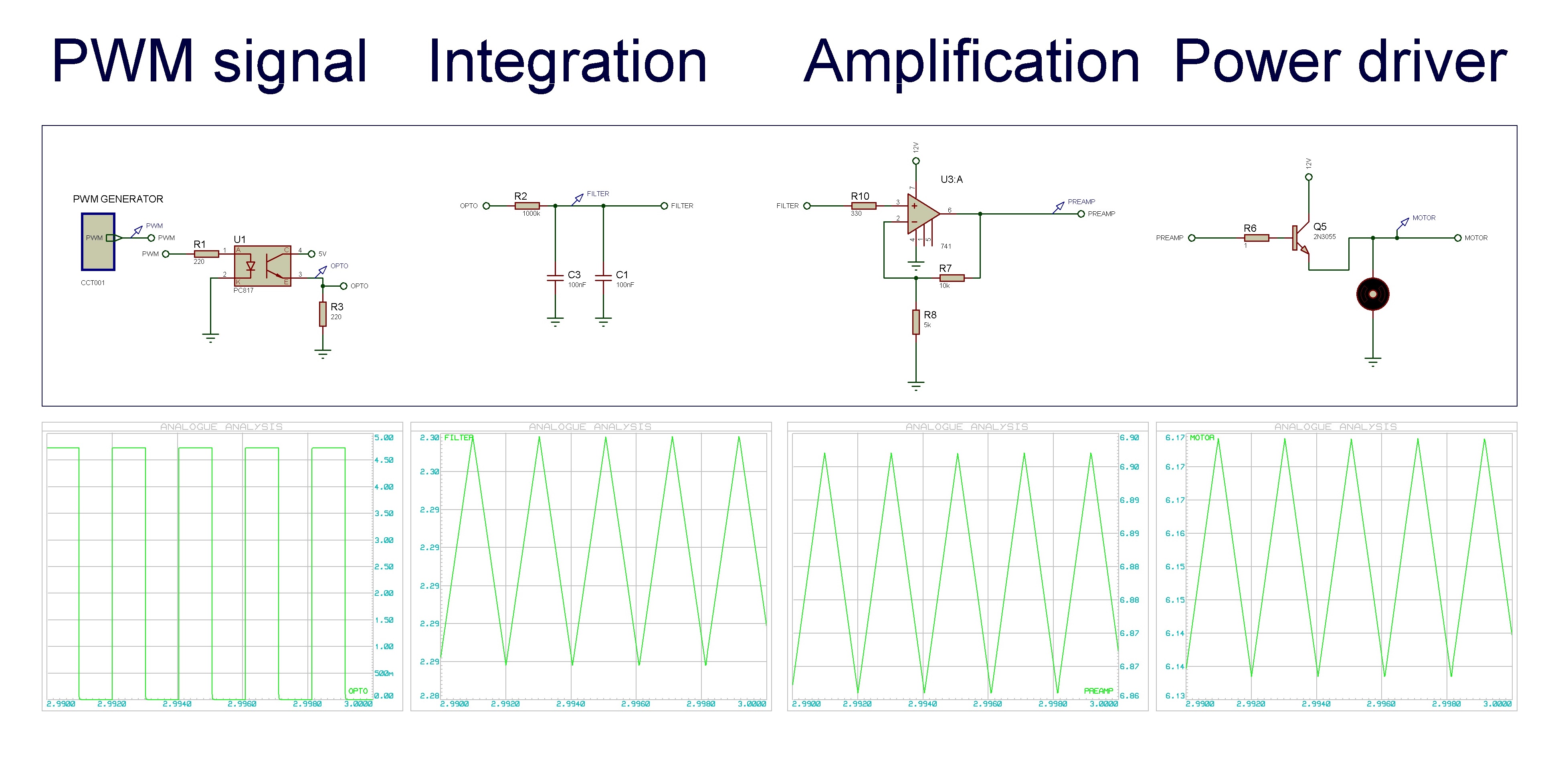
Project schematic:
A fast brief.
How to test it: Once downloaded and opened proteus file, Send characters 0 to 5 through the virtual terminal to easyly set the PWM duty, this was done like this for testing purpouses. As shown in this video:
We work on TTL so:
Vpwm = 5v
As output a DC motor with full variable values, current will vary depending on the resistance applyed on the rotor, and voltage by the PWM.
Motor Voltage Range=0v-12v
Motor Current Range= 0A-10A
Explanation
1. PWM signal.
No problems with this. An arduino creates a signal via analogWrite, ino file included in sources.
2. Integration.
In order to convert incoming signal from PWM into a integrated signal, I built up this Rc filter, I can see is not the best one because R2 is too high and its take to long to become stable.
I would like to inprove this in order to flaten the signal. Is the way Im using correct?
3. Amplification.
A Non-Inverting Operational Amplifier will amplify the voltage of the integrated signal X2 volts aprox, in order to create 0-12 volts from a 0-5 volts range.
Should I use a BC547 or TIP31 or any BJT transistor? or OPAMP is better, I think the second one is more appropiate but I may be wrong.
4. Power driver
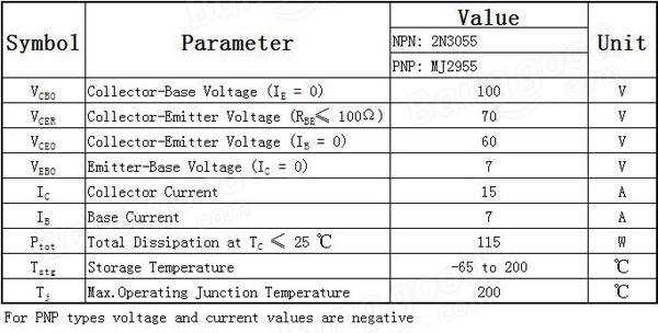
I have to use a 2n3055 transistor because i have it, and because due to hardware settings it has to be npn.
He is able to work in the power range I need as we can see in the table above.
I reached the resistor values by empirically trying with proteus, thats why i have serious doubts about if its right.
I dont know how make it safe and be sure. It seems it works, but I dont know if this is the best way.
2n3055 table
Questions
I would like to read your opinions and critics before I start building it, and I would be very thankful with al advises and proposals.
I have created a circuit in proteus and it works, kinda cool, but, I have the feeling it has to be inproved and some questions about Integrating the signal and how the transistor 2n3055 works. I would like somebody elses opinions and corrections.
The target is to regulate the voltage of a load via PWM duty and 2n3305 transistor.
Resources:
Proteus files : https://drive.google.com/drive/folders/1EYbGP7WJoEnfO8Z9XC5a5SSe4Bv2Sw18?usp=sharing
Project schematic:
A fast brief.
How to test it: Once downloaded and opened proteus file, Send characters 0 to 5 through the virtual terminal to easyly set the PWM duty, this was done like this for testing purpouses. As shown in this video:
We work on TTL so:
Vpwm = 5v
As output a DC motor with full variable values, current will vary depending on the resistance applyed on the rotor, and voltage by the PWM.
Motor Voltage Range=0v-12v
Motor Current Range= 0A-10A
Explanation
1. PWM signal.
No problems with this. An arduino creates a signal via analogWrite, ino file included in sources.
2. Integration.
In order to convert incoming signal from PWM into a integrated signal, I built up this Rc filter, I can see is not the best one because R2 is too high and its take to long to become stable.
I would like to inprove this in order to flaten the signal. Is the way Im using correct?
3. Amplification.
A Non-Inverting Operational Amplifier will amplify the voltage of the integrated signal X2 volts aprox, in order to create 0-12 volts from a 0-5 volts range.
Should I use a BC547 or TIP31 or any BJT transistor? or OPAMP is better, I think the second one is more appropiate but I may be wrong.
4. Power driver
I have to use a 2n3055 transistor because i have it, and because due to hardware settings it has to be npn.
He is able to work in the power range I need as we can see in the table above.
I reached the resistor values by empirically trying with proteus, thats why i have serious doubts about if its right.
I dont know how make it safe and be sure. It seems it works, but I dont know if this is the best way.
2n3055 table
Questions
I would like to read your opinions and critics before I start building it, and I would be very thankful with al advises and proposals.