Andrei Bului
- Dec 20, 2016
- 3
- Joined
- Dec 20, 2016
- Messages
- 3
Hi. I am new on this forum but I would really appreciate some help on this one.
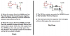
So basically I have this RGB LED controller that has a switch that switches between them being ON ( connected directly to ground ) and them dancing on music. It's just a transistor getting input to it's base from the sound input. I have 2 channels. Left and Right. The other jack is just for having a in-built spliter so I can connect some speakers to it and easier access to the Right channel. The transistor type is a TIP31C ( thus the base and collector being inversed ) and the Op-Amp is a LM386 and i marked the pins for you. The pin 1 and 8 are used only for gain which I don't care about and the 7-th pin is for bypass. I forgot to add a 220uF capacitor between the Vout's and the Stereo potentimeter which controls the reactivity of the LEDs to the music.
Now what's not working:
I've made this circuit before, a little bit modified ( Had only one channel ) and it worked. When I had the LEDs connected they where shining dimly. As soon as I connected a male jack into the female jack they went off completely and when I started the music, everything went fine. The LEDs were blinking properly on the music. I tried to redo the circuit step by step by adding the other channel and nothing is working anymore. When I switch to "music mode" they go off ( they dont shine dimly anymore ) and when I connect the male jack nothing happens, when I input music, also nothing happens. NOTE: My phone doesn't show the headphone in symbol if I have voltage in the circuit and the phone connected to it. If I turn the voltage ( the circuit ) off it shows me that it is connected. So is it something wrong with my circuit? Is something connected the way it should not be? I want to note that this circuit is made by me.I tried to draw it :

And included a schematic:
I hope I included enough details and I also hope that I will find help on this forum. Please, I really need it to work!
Thanks in advance and if more information is needed ask and I will try to provide.
So basically I have this RGB LED controller that has a switch that switches between them being ON ( connected directly to ground ) and them dancing on music. It's just a transistor getting input to it's base from the sound input. I have 2 channels. Left and Right. The other jack is just for having a in-built spliter so I can connect some speakers to it and easier access to the Right channel. The transistor type is a TIP31C ( thus the base and collector being inversed ) and the Op-Amp is a LM386 and i marked the pins for you. The pin 1 and 8 are used only for gain which I don't care about and the 7-th pin is for bypass. I forgot to add a 220uF capacitor between the Vout's and the Stereo potentimeter which controls the reactivity of the LEDs to the music.
Now what's not working:
I've made this circuit before, a little bit modified ( Had only one channel ) and it worked. When I had the LEDs connected they where shining dimly. As soon as I connected a male jack into the female jack they went off completely and when I started the music, everything went fine. The LEDs were blinking properly on the music. I tried to redo the circuit step by step by adding the other channel and nothing is working anymore. When I switch to "music mode" they go off ( they dont shine dimly anymore ) and when I connect the male jack nothing happens, when I input music, also nothing happens. NOTE: My phone doesn't show the headphone in symbol if I have voltage in the circuit and the phone connected to it. If I turn the voltage ( the circuit ) off it shows me that it is connected. So is it something wrong with my circuit? Is something connected the way it should not be? I want to note that this circuit is made by me.I tried to draw it :
And included a schematic:
I hope I included enough details and I also hope that I will find help on this forum. Please, I really need it to work!
Thanks in advance and if more information is needed ask and I will try to provide.