Maker Pro
Maker Pro

Running high current electric solenoid using a H-bridge

Jimbo bob

Oct 8, 2014
45
Joined
Oct 8, 2014
Messages
45
Hi dear enthusiasts:D,

I am planning to run a push/pull 21 lb force electric solenoid. It takes an input of 12 V and demands around 35 Amps (instantaneous I believe) to move between pushed and pull positions. I am planning to run it using a H-bridge with PWM capability. I am hoping to use the PWM capability that comes along with H-bridge to control how far of push/pull I get out of the solenoid. I have a control unit to produce the PWM signal and an AG801 8-Cell (light weight lithium-iron battery) to provide the current for driving the solenoid.
Here is the link of the H-bridge I am using. (click on the word "link").

I have two concerns however:

The battery manufacturer only provides stats which are relevant and in comparison to a lead-acid battery. So, overall I am not sure whether the battery will support solenoid’s instantaneous draw. Also for the sake of argument imagine the battery has other loads on it similar to a car.


Secondly, to overcome the instantaneous current draw (if it turns out to become troublesome) I am thinking whether it is possible to use PWM to power the solenoid itself. So, not only use a PDM signal to control solenoids position, but also power it. Is this a possible option and does it make any difference in my case?

Any ideas, hints or resources are much appreciated.
Many thanks in advance!!! :):)
 

hevans1944

Hop - AC8NS
Jun 21, 2012
4,880
Joined
Jun 21, 2012
Messages
4,880
I seriously doubt you want to run a solenoid with an H-Bridge. The H-Bridge is typically used when you need to reverse the polarity applied to a load, as in a reversible motor direction. It is also impossible to control with PWM how far a push/pull solenoid moves unless there is a restoring spring to apply a force that counteracts against the force applied by the solenoid armature. If that's the case... go for it. Be aware that magnetic fields do not produce a linear force versus current and plan accordingly. The inductance of the solenoid might be a hindrance to effective PWM current control however because said inductance opposes any change in current.

Can you provide more information (datasheets, manufacturer's name and model number) of the solenoid and the battery you are planning to use?
 

Jimbo bob

Oct 8, 2014
45
Joined
Oct 8, 2014
Messages
45
Hi hevans1944 :),

I seriously doubt you want to run a solenoid with an H-Bridge.
Hmmm....I wonder why not? I was hoping by reversing the current's direction through the H-bridge reverse the direction of the motion of the solenoid (i.e. switch between push and pull), the same way the direction of motion of a motor connected to a H-bridge changes. Also here is a link to a product that does this. Here is another link explaining that this is possible with a H-bridge. For some reason they refer to the circuit as Dual H-bridge, but I do not understand why is it dual, or why would you need a Dual H-bridge when one H-bridge can provide two directions of motion?
It is also impossible to control with PWM how far a push/pull solenoid moves unless there is a restoring spring to apply a force that counteracts against the force applied by the solenoid armature.
This article makes a suggestion how PWMing the input of the H-bridge can allow for position control apparently. I think it is on page 7 onward.
Can you provide more information (datasheets, manufacturer's name and model number) of the solenoid and the battery you are planning to use?

Link to the battery page:
http://antigravitybatteries.com/ag-801/

Here are the specs of the solenoid I am going to use. Unfortunately I could not find a datasheet for it, but one can see it in Kliktronic website, in the technical tab and under the actuator assembly tab:

Dimensions & Electrical specifications
Length (body): 150mm - Diameter: 50mm - Length of connecting rod (6mm dia) : 80mm extended - 30mm retracted
Power consumption Amps (nominal 12volt supply) : Standard : 35A - High Power: 48A -
Weight 1.5Kg

Here are the rest of the links I have used in my reply regarding the H-bridge and solenoid control, in case they did not open above:
http://www.ti.com/lit/an/slva460/slva460.pdf
http://www.motec.com.au/dhb/dhboverview/

Also thanks again for your reply. It is quite informative :).
 

Jimbo bob

Oct 8, 2014
45
Joined
Oct 8, 2014
Messages
45
The plunger or core has to be a magnet to reverse the direction of travel.
Yes. That makes sense. I am pretty sure this one is because in their website they show that they use it for shifting gears electronically in motor bikes to help disabled individuals. So it has to be able to both pull and push to up-shift and down-shift gears.
 

hevans1944

Hop - AC8NS
Jun 21, 2012
4,880
Joined
Jun 21, 2012
Messages
4,880
Yes. That makes sense. I am pretty sure this one is because in their website they show that they use it for shifting gears electronically in motor bikes to help disabled individuals. So it has to be able to both pull and push to up-shift and down-shift gears.
And the actuator rod "floats" on the foot-shift mechanism (no spring inside), so as not to interfere with shifting by non-disabled riders, which is a good idea if you share your MC or later want to sell it. The Kliktronic, according to their website, is easy to install and just as easy to remove. There are also interesting comments about how this product came into existence, why it has no patent protection, and more. Well worth a visit if you ride, but the product is a bit pricey IMHO. Well, maybe not so pricey for a niche product practically hand-made.

It is not possible to determine from the "Technical" page on the Kliktronic website whether their purpose-built (not off-the-shelf) solenoid has a magnet attached to the actuator rod like @Colin Mitchell stated, or whether it simply has two coils... one for extension and one for retraction. Based on this PDF installation manual (see page 13), it has two coils, one for up-shift, one for down-shift. Both coils are driven positive with respect to a common vehicle ground. You don't need an H-bridge for that. Two power MOSFETs and two diodes to protect them will do it.

Snippet of text from page 13 of the installation manual:

Should you need to alter any of the wiring then the
plugs/sockets are wired as follows:

3 Pin Actuator plug/socket

Pin 1-Green wire up-shift positive supply (rod retracts)
Pin 2-Black wire-common negative
Pin 3-White wire down-shift positive supply (rod extends)

4 Pin Switch plug/socket

Pin 1-Green/yellow wire trigger for up-shift circuit
Pin 2-Unused
Pin 3-Brown wire, common supply for both switches
Pin 4-Blue wire, trigger for down-shift circuit

You may be able to energize both coils simultaneously and vary the current in them independently with PWM, allowing you to position the actuator rod at arbitrary positions within its one-inch stroke. Be careful not to burn out the coils by applying power continuously. The solenoid coils are designed for intermittent operation only.

Are you going to use the solenoid for its intended purpose, to shift gears on a motorcycle?
.
 
Last edited:

Jimbo bob

Oct 8, 2014
45
Joined
Oct 8, 2014
Messages
45
And the actuator rod "floats" on the foot-shift mechanism (no spring inside), so as not to interfere with shifting by non-disabled riders, which is a good idea if you share your MC or later want to sell it. The Kliktronic, according to their website, is easy to install and just as easy to remove. There are also interesting comments about how this product came into existence, why it has no patent protection, and more. Well worth a visit if you ride, but the product is a bit pricey IMHO. Well, maybe not so pricey for a niche product practically hand-made.

It is not possible to determine from the "Technical" page on the Kliktronic website whether their purpose-built (not off-the-shelf) solenoid has a magnet attached to the actuator rod like @Colin Mitchell stated, or whether it simply has two coils... one for extension and one for retraction. Based on this PDF installation manual (see page 13), it has two coils, one for up-shift, one for down-shift. Both coils are driven positive with respect to a common vehicle ground. You don't need an H-bridge for that. Two power MOSFETs and two diodes to protect them will do it.

Snippet of text from page 13 of the installation manual:

Should you need to alter any of the wiring then the
plugs/sockets are wired as follows:

3 Pin Actuator plug/socket

Pin 1-Green wire up-shift positive supply (rod retracts)
Pin 2-Black wire-common negative
Pin 3-White wire down-shift positive supply (rod extends)

4 Pin Switch plug/socket

Pin 1-Green/yellow wire trigger for up-shift circuit
Pin 2-Unused
Pin 3-Brown wire, common supply for both switches
Pin 4-Blue wire, trigger for down-shift circuit

You may be able to energize both coils simultaneously and vary the current in them independently with PWM, allowing you to position the actuator rod at arbitrary positions within its one-inch stroke. Be careful not to burn out the coils by applying power continuously. The solenoid coils are designed for intermittent operation only.

Are you going to use the solenoid for its intended purpose, to shift gears on a motorcycle?
.

Thanks for your thorough reply:D. It makes more sense to me now and I see that there will not be necessarily any need for a H-bridge, since there are two separate coils and two MOSFETs should do the job. Then using a PWM pulse to the MOSFETs I need to find the desirable position that I would like to put the actuator at.

Well worth a visit if you ride, but the product is a bit pricey IMHO. Well, maybe not so pricey for a niche product practically hand-made.
Yeah, it is pricey:(. They have a control box which comes as a part of the kit. I believe that is capable of only extending/retracting the solenoid half-way (which is where I am trying to put it using PWM). This is because the neutral gear on many motorcycles is a half-shift.

Are you going to use the solenoid for its intended purpose, to shift gears on a motorcycle?

Not exactly. At the moment I am planing to experiment only, to get an idea about controlling a solenoid like Kliktronic's and electrical circuitry required for it to achieve a full up and down shift as well as a half-shift. For me to actually implement this on a real motorcycle, I will need to examine the risks and hazards associated with it and I will not discuss its actual implementation on this forum due to the forum policies. Nonetheless, in my experimentation I am assuming the constraints and environmental characteristics associated with a motorcycle. For example, this is why I mentioned a specific battery before which is used on some motorcycles.:)
 

Colin Mitchell

Aug 31, 2014
1,416
Joined
Aug 31, 2014
Messages
1,416
To get half-shift, the item you are operating must stay in the designated position AFTER the current is removed. You will need a micro switch in the mid-position to provide feedback as the energy (strength) to achieve mid-position will vary from day to day.
You can also consider 2 cheaper push-solenoids (pull-solenoids) back-to-back.
 

Jimbo bob

Oct 8, 2014
45
Joined
Oct 8, 2014
Messages
45
To get half-shift, the item you are operating must stay in the designated position AFTER the current is removed. You will need a micro switch in the mid-position to provide feedback as the energy (strength) to achieve mid-position will vary from day to day.
You can also consider 2 cheaper push-solenoids (pull-solenoids) back-to-back.
You raise an interesting point. In this instance (i.e. shifting the gear) I want the solenoid to reach a certain length threshold (i.e. half-shift), but that would be enough for shifting the gear. I doubt that I would require it to stay in that position, but only reach it and shift the gear. I am sorry for not clarifying this earlier, but here is a video which shows how the solenoid shifts between the gears including the neutral which is a half-shift:
 

Colin Mitchell

Aug 31, 2014
1,416
Joined
Aug 31, 2014
Messages
1,416
Don't try re-inventing the wheel. Go to the person who produced the video and ask for the details of the invention.
 

Jimbo bob

Oct 8, 2014
45
Joined
Oct 8, 2014
Messages
45
Don't try re-inventing the wheel. Go to the person who produced the video and ask for the details of the invention.
Sure thing. That is a good advice. Nonetheless, the people who made the video are indeed using the Kliktronic "control box" and solenoid. Kiliktronic people are selling the control box and the solenoid and a few other items as a kit. They maybe rightfully hesitant about sharing that sort of information about the circuitry they use in that control box (even though I will ask) and they probably prefer it if I paid for it and not made my own cheaper version. Moreover, I am a bit tight on budget and if I could control the solenoid with a couple of transistors and diodes, I will be better off financially perhaps. After all, the off the shelf equipment is rather pricey.
 

davenn

Moderator
Sep 5, 2009
14,260
Joined
Sep 5, 2009
Messages
14,260
After all, the off the shelf equipment is rather pricey.

probably, partly for a good reason ... there's been some decent research done to design and build the unit
and it was found to take more than a couple of transistors and diodes


D
 

hevans1944

Hop - AC8NS
Jun 21, 2012
4,880
Joined
Jun 21, 2012
Messages
4,880
The Kliktronic dual-coil solenoid is the only thing you need to purchase from Kliktronic. They had someone engineer the two coils and the actuator armature (the part that interacts with the magnetic fields of the coils) to produce the stroke they needed (one inch) at the force and speed they determined would be sufficient to actuate the gear-change mechanism. I would bet you have to pay a pretty significant portion of the "kit" price to buy just the solenoid.

Having a floating armature (most solenoid armatures have a spring-return mechanism) closely resembles the foot-action of a motorcycle rider. I only touched my foot to the shifter when I actually wanted to shift, making it a habit to punch down multiple times with my left foot while slowing to a stop with the clutch disengaged, to make sure I stopped with the bike in first gear. It is sooo embarrassing to try to start the bike from third gear (or higher) and have the engine stall when the clutch is engaged. That said, I can't think of a better way to emulate the action of a rider's foot than to use a floating armature with two solenoids that move it to two different positions.

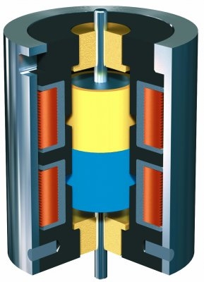
You could possibly get a similar effect with a rare-earth magnet and a single solenoid, reversing the field as @Colin Mitchell mentioned in his post #4. However, I see all sorts of problems with this. The force on the permanent magnet will be greatest when it is positioned near the center of the coil. Reversing the current in the coil will cause a torque to be applied to the permanent magnet as well as a decreasing coaxial force that will drive is out of the center of the coil. Who knows what the consequences of such a design are? OTOH, if you design the permanent magnet to always be outside the core of the coil, then you will need magnetic pole pieces inside the solenoid coil, acting against the poles of the permanent magnet, to provide efficient magnetic coupling to the armature. This is not a good arrangement if you want substantially equal push versus pull strength and speed during the time the coil is energized. It also means the permanent magnet will be attracted to and stick to the pole piece protruding from the coil when the coil is not energized.

Maybe I just lack imagination, but I cannot envision a single arrangement of permanent magnet (or magnets) and single solenoid coil (with or without magnetic pole pieces) that will result in equal push/pull forces when current is applied to the solenoid coil in alternating polarity. Two tandem coils, each actuating the same armature, seems to be the simplest solution, as well as an elegant solution.

BTW, the problem of finding neutral while up-shifting is easily overcome with practice. For the Kliktronic product, the key appears to be a light, quick tap of the up-shift button. This will apply an impulse of momentum to the shift lever sufficient to disengage first gear without enough force to engage second gear. Which also implies that the "control box" is just a pair of MOSFETs or IGBTs interfacing between the push-button switches and the coils, perhaps with circuitry to prevent both coils from actuating simultaneously. Piece of cake for someone here to lash up a circuit for that.

Moving the armature (actuator rod) to a particular position? Not so easy. Magnetic forces are nonlinear like you would not believe until you actually "feel" them. But here is a place (in France) to start looking. And maybe visit this web page too. IIRC, most linear magnetic actuators require negative position feedback to operate in a stable manner... not a big deal with modern electronics, but still an additional complexity. Comments?

ring-magnet-linear-actuator-with-high-locking-force11.jpg
 
Last edited:

Jimbo bob

Oct 8, 2014
45
Joined
Oct 8, 2014
Messages
45
The Kliktronic dual-coil solenoid is the only thing you need to purchase from Kliktronic. They had someone engineer the two coils and the actuator armature (the part that interacts with the magnetic fields of the coils) to produce the stroke they needed (one inch) at the force and speed they determined would be sufficient to actuate the gear-change mechanism. I would bet you have to pay a pretty significant portion of the "kit" price to buy just the solenoid.

Having a floating armature (most solenoid armatures have a spring-return mechanism) closely resembles the foot-action of a motorcycle rider. I only touched my foot to the shifter when I actually wanted to shift, making it a habit to punch down multiple times with my left foot while slowing to a stop with the clutch disengaged, to make sure I stopped with the bike in first gear. It is sooo embarrassing to try to start the bike from third gear (or higher) and have the engine stall when the clutch is engaged. That said, I can't think of a better way to emulate the action of a rider's foot than to use a floating armature with two solenoids that move it to two different positions.

You could possibly get a similar effect with a rare-earth magnet and a single solenoid, reversing the field as @Colin Mitchell mentioned in his post #4. However, I see all sorts of problems with this. The force on the permanent magnet will be greatest when it is positioned near the center of the coil. Reversing the current in the coil will cause a torque to be applied to the permanent magnet as well as a decreasing coaxial force that will drive is out of the center of the coil. Who knows what the consequences of such a design are? OTOH, if you design the permanent magnet to always be outside the core of the coil, then you will need magnetic pole pieces inside the solenoid coil, acting against the poles of the permanent magnet, to provide efficient magnetic coupling to the armature. This is not a good arrangement if you want substantially equal push versus pull strength and speed during the time the coil is energized. It also means the permanent magnet will be attracted to and stick to the pole piece protruding from the coil when the coil is not energized.

Maybe I just lack imagination, but I cannot envision a single arrangement of permanent magnet (or magnets) and single solenoid coil (with or without magnetic pole pieces) that will result in equal push/pull forces when current is applied to the solenoid coil in alternating polarity. Two tandem coils, each actuating the same armature, seems to be the simplest solution, as well as an elegant solution.

BTW, the problem of finding neutral while up-shifting is easily overcome with practice. For the Kliktronic product, the key appears to be a light, quick tap of the up-shift button. This will apply an impulse of momentum to the shift lever sufficient to disengage first gear without enough force to engage second gear. Which also implies that the "control box" is just a pair of MOSFETs or IGBTs interfacing between the push-button switches and the coils, perhaps with circuitry to prevent both coils from actuating simultaneously. Piece of cake for someone here to lash up a circuit for that.

Moving the armature (actuator rod) to a particular position? Not so easy. Magnetic forces are nonlinear like you would not believe until you actually "feel" them. But here is a place (in France) to start looking. And maybe visit this web page too. IIRC, most linear magnetic actuators require negative position feedback to operate in a stable manner... not a big deal with modern electronics, but still an additional complexity. Comments?

@hevans1944 Wow:)! This is a very thorough response:D!! Thank you very much for that. I think I understand what you are talking about and how a single solenoid case could become quite tricky to control.

Depending on the application (?) a linear actuator may be a better idea
https://en.wikipedia.org/wiki/Linear_actuator
@GPG That is a good point and thanks for bringing it up:).
 

Jimbo bob

Oct 8, 2014
45
Joined
Oct 8, 2014
Messages
45
You could possibly get a similar effect with a rare-earth magnet and a single solenoid, reversing the field as @Colin Mitchell mentioned in his post #4. However, I see all sorts of problems with this. The force on the permanent magnet will be greatest when it is positioned near the center of the coil. Reversing the current in the coil will cause a torque to be applied to the permanent magnet as well as a decreasing coaxial force that will drive is out of the center of the coil. Who knows what the consequences of such a design are? OTOH, if you design the permanent magnet to always be outside the core of the coil, then you will need magnetic pole pieces inside the solenoid coil, acting against the poles of the permanent magnet, to provide efficient magnetic coupling to the armature. This is not a good arrangement if you want substantially equal push versus pull strength and speed during the time the coil is energized. It also means the permanent magnet will be attracted to and stick to the pole piece protruding from the coil when the coil is not energized.

Hi @hevans1944,

I did post this link earlier, but I was not sure whether you did have a look at it or not. Nonetheless, I found it interesting because it is relevant to what you mentioned about having a single solenoid and another magnet. It also does mention using PWM to control the solenoid's position on page 7 I think.
 

hevans1944

Hop - AC8NS
Jun 21, 2012
4,880
Joined
Jun 21, 2012
Messages
4,880
I did read the application note, but without opposing coils see no way to move the actuator to a particular position. Sorry, but that's just the way magnetic fields work, permanent magnets or not attached to the actuator.
 

davenn

Moderator
Sep 5, 2009
14,260
Joined
Sep 5, 2009
Messages
14,260
Hi @hevans1944,

I did post this link earlier, but I was not sure whether you did have a look at it or not. Nonetheless, I found it interesting because it is relevant to what you mentioned about having a single solenoid and another magnet. It also does mention using PWM to control the solenoid's position on page 7 I think.

yes you can but note the text.....

2.3 INx Input PWM


In some applications, it is beneficial for the solenoid load to be PWM’d. This offers the capability to control

the current the inductive component sees, yielding a directly proportional magnetic field and a


predetermined position. INx inputs can be safely PWM’d. However, to close the loop the user must read


the current information from the SENSE resistor. This technique will not work if there are two solenoids


being driven by the same H-Bridge.


If current regulation is needed as to obtain directly proportional position control, we recommend the usage

of a full H-Bridge per solenoid load. A myriad of DRV88xx devices already contain current regulation so it

would be a matter of administering the correct VREF value, and current would be regulated according to

its respective ITRIP equation. Each device’s datasheet will contain the information on how to regulate

current and its respective ITRIP equation.


particularly the bit in red
there would need to be 2 separate H-bridges, one controlling each solenoid
 

Jimbo bob

Oct 8, 2014
45
Joined
Oct 8, 2014
Messages
45
yes you can but note the text.....

2.3 INx Input PWM


In some applications, it is beneficial for the solenoid load to be PWM’d. This offers the capability to control

the current the inductive component sees, yielding a directly proportional magnetic field and a


predetermined position. INx inputs can be safely PWM’d. However, to close the loop the user must read


the current information from the SENSE resistor. This technique will not work if there are two solenoids


being driven by the same H-Bridge.


If current regulation is needed as to obtain directly proportional position control, we recommend the usage

of a full H-Bridge per solenoid load. A myriad of DRV88xx devices already contain current regulation so it

would be a matter of administering the correct VREF value, and current would be regulated according to

its respective ITRIP equation. Each device’s datasheet will contain the information on how to regulate

current and its respective ITRIP equation.


particularly the bit in red
there would need to be 2 separate H-bridges, one controlling each solenoid

Based on what I have understood from what you and @hevans1944 have talked about is that if I am going to be using a single coil solenoid, I have to use a closed-loop feedback system and a sensor (i.e. like a servo motor) if I want the piston to move to a particular position. However, if I only want the piston to extend and retract and move maybe just halfway (i.e. up-shift, down-shift and neutral), would it be necessary for me to actually design a controller for my solenoid or would I just be able to have a circuitry just for "half-energizing" the to get to the neutral gear (though trial and error). This is my understanding and I may be wrong, but I am thinking a controller like the one used on servos, allows them to move to a variety of angles using PWM, but I only have 3 positions that want my solenoid to move my piston to (i.e. up-shift, down-shift and neutral), so would not designing a controller be kind of an "over-kill", practically speaking. (Also for now I am only assuming a single coil solenoid, not like the ones that Kliktronic offer).

On a different note, I have been looking into getting my hands on Kliktronics solenoid and similar solenoids from other vendors (i.e. the ones with two coils in them as discussed before). Not surprisingly, as mentioned before by you guys, Kliktronic products happen to be quite pricey and just buying the solenoid would cost me around $550 AU :(. I am still trying to see whether I could find similar products of some other brands which are perhaps second-hand or cosmetically damaged, for a cheaper price.

The other options that I am looking into are maybe somehow using a single coil push/pull solenoid and also if I can find any fast and cheap enough linear actuators mentioned by @GPG . Nonetheless, the linear actuators so far seem to be a bit slow for what I am trying to achieve.

Looking forward to hearing your thoughts on this!!:)
 

hevans1944

Hop - AC8NS
Jun 21, 2012
4,880
Joined
Jun 21, 2012
Messages
4,880
@Jimbo bob: Okay, what ARE you trying to DO? Do you ride a motorcycle? If so, what is the year, make, and model? Are you disabled and incapable of foot-shifting? Are you trying to help a disabled person who wants to ride? Do you want to power-shift with the clutch engaged by interrupting the ignition? Do you race? Please tell us what the end-game is, as I see this thread going nowhere without specific hardware goals.

You posted a video showing a Kliktronic Gear Change on a Honda Deauville crotch-rocket that basically started from N, down-shifted to 1 and then ran up through the gears to 5 and then down-shifted back down to 1 before finally up-shifting into N. That last "shift" to N was accomplished with a short-pulse to up-shift from 1 to N (basically taking it out of gear) without enough impulse to push the shift lever through the N position to 2nd gear.

This is all very familiar to a rider who shifts with their left foot. You soon get a "feel" for how much boot action is required to up-shift from 1st gear into neutral. Down shifting is a similar feeling, but I usually overshot the N position and wound up in 1st gear if N was where I wanted to be... like when idling at a long stop with the clutch lever released. Or sometimes I would hit N while aiming for 1st and forget it was still in N when the light changed to green. Another embarrassing senior moment, especially if riding with friends. So, upon stopping, I would down-shift repeatedly to make sure I was in 1st gear. You can't go any lower than 1st, but there is no harm in making sure you really are there before trying to move again.:p

All of that applies to modern motorcycles. The earlier ones had different arrangements for clutch and shift levers. We won't go there. Modern shift levers have a spring-return to a "center position" that is moved to either side of center to shift gears up and down. The foot lever is lifted up with toe of the boot to up-shift and pressed downward to down-shift. Neutral (all gears disengaged) is between 1st gear and 2nd gear. This is why a solenoid actuator has to be free-floating when attached to the gear lever. It must allow the gear lever to return to its spring-loaded center position between shifts. Note in the video that the solenoid also pivots slightly to accommodate the arc through which the shift lever moves. It makes almost no sense to me that you would want the shift lever to ever assume and hold a half-shift position when shifting into neutral from either 1st gear or 2nd gear. What you want it to do is disengage either 1st gear or 2nd gear without moving far enough to engage the next gear whether up-shifting or down-shifting. That only requires a short impulse from the solenoid armature (what you are calling the piston) instead of a steady sustained shove which occurs if the solenoid stays energized.

I suppose you could add a third shift button, to be used only to shift from 1st to N or from 2nd to N, and you possibly could gin up something (maybe a third or fourth coil?) to make the shift lever move to a so-called half-shift point and stay there until you released the third button. Note there would be two "half-shift" positions corresponding to shift up from 1st to N and shift down from 2nd to N. Heck, we could get even more fancy and add electronics that would "find" N from any gear! But for me, that ain't what MC riding is about. Wind in your face, an open road with some spiffy curves, a friend on the back, and a full tank of gas that didn't require a second mortgage... that's what MC riding is to me. I don't spend a whole lot of time trying to find Neutral gear.:cool:

Hop
 
Top