WhiteSmith
- Jul 25, 2015
- 6
- Joined
- Jul 25, 2015
- Messages
- 6
Hello everyone!
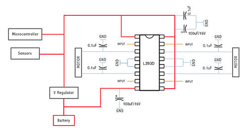
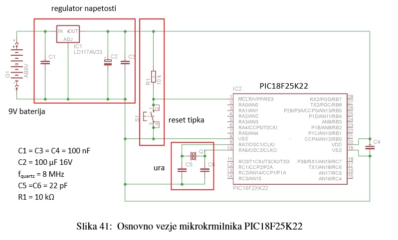
I'm a student of Mechatronics and I have a project in which I have to make a robot that is run by two Y-3009 Modelcraft servos. I have already made a PIC basic circuit with the Quartz crystal and the reset button etc., and also the one with the H-bridge. I made the exact same circuit that is shown in this thread http://www.instructables.com/id/Control-your-motors-with-L293D-and-Arduino/. This was the circuit that my mentor proposed I should use. But now I stumbled into a bit of a problem... I understand I have to mechanically alter my two servos in order to get them working for this concept. I already removed the mechanical protection that disallows the servo to exceed its limits and I shortened the potentiometer so that it is always positioned in its starting position http://www.instructables.com/id/How-to-modify-a-servo-motor-for-continuous-rotatio/. So now my servo should be acting as a DC motor if I understand correctly? Now if I return to the H-bridge... Which two lines do I have to connect to the outputs? Is it the + and ground? or is it the signal and ground? Or maybe even + and signal? An educated guess would say it is the + and ground. And in this case or the previous ones, which one goes where (which goes on which pin of the bridge)? When I correctly plug my servo on the bridge there is still the matter of connecting the bridge to the PIC. There are four pins reserved for the input on the L293D. Which ports of the PIC do I have to route to each pin on the H-bridge? And when I do that, How do I control the motors? I understand it is with PWM? But if it is so, how do I control the direction which the servo should be turning?
So if anyone ever made anything similar, I would really appreciate it if you could clarify the situation for me or maybe give me some useful links so I could also write which literature I was using?
I would also like to apologize for my poor English, as I am not a native speaker. Hopefully everything is understood and if not, I will be more than happy to clarify any misunderstandings.
Thanks in advance!