Maker Pro
Maker Pro

Serial communication problem.

HellasTechn

Apr 14, 2013
1,579
Joined
Apr 14, 2013
Messages
1,579
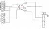
Ok i understand your point. Serial port is OK and the circuit is correct.

The "problem" was not a problem but a product of my silly thinking. Nothing more.

I would like to thank you sir Chris for all the effort you put to teach me serial communication !
 

HellasTechn

Apr 14, 2013
1,579
Joined
Apr 14, 2013
Messages
1,579
Good day to you all !

I am back digging out this old thread to ask a few questions about a few things i have noticed about the circuit below.

It is a Picaxe Microcontroller that receives ttl level rs232 signal from the simple transistor rs232 to ttl converter.
the transistors used are BC547 (npn) (cbe).
Before anything else i would like to point out that the transistors are placed in reverse active mode (emitter to vcc and collector to gnd) because this is the only way the picaxe will read the ttl signal correctly. Why ? i have no idea. Oscope images are identical for both forward biased and reverse biased transistor like shown in earlyer posts.

Now the circuit is exactly as shown on the picture below (only all unused picaxe inputes and outputs are pulled low via 10k resistors)

Scoping 1 shows the rs232 signal fed to the transistor base via the 10k resistor.
scoping 2 shows the signal at the base of the transistor after the 10k resistor and the 1n4148 diode.
scoping 3 shows the signal at the emitter of the transistor.

now the diode is present to send to ground the negative pulses of the rs232 signal to protect the transistors positive base.
1st question: Why do i see the pulse going negative 500mv at the base ? will it not eventually kill the transistor ?
2nd question: Could that be affecting somehow the fact that picaxe can not read while the transistor is placed forward biased ? (collector to vcc and emmiter to ground?).

P.S
the shadow you see on picture 3 is because i failed to capture the picture fast enough.
 

Attachments

  • RS232 SIGNAL.PNG
    RS232 SIGNAL.PNG
    8.7 KB · Views: 84
  • AT BASE.PNG
    AT BASE.PNG
    8.7 KB · Views: 60
  • AT EMITTER.PNG
    AT EMITTER.PNG
    9.8 KB · Views: 52
  • circuit.png
    circuit.png
    25.6 KB · Views: 57

HellasTechn

Apr 14, 2013
1,579
Joined
Apr 14, 2013
Messages
1,579
I do have one and the diodes appear to be functioning correctly. I will replace them with new just in case. Beleave me, next step would be for me to ship the pcb to you so that you can examine it for your self. :)
 
Last edited:

HellasTechn

Apr 14, 2013
1,579
Joined
Apr 14, 2013
Messages
1,579
I further tested and i think i came to a conclusion about this weird scopings ive got.

On the breadboard i assembled the following circuit exactly as pictured and fed it with -5V from a symmetric psu

on the oscope screen i got a -700mv voltage.

Conclusion: the negative voltage seen on the base of the transistor is obviously the the diodes forward voltage Vf.
I confirmed it with the diode meter, giveing me a Vf value around 700mv.
 

Attachments

  • test circuit.png
    test circuit.png
    11 KB · Views: 75

HellasTechn

Apr 14, 2013
1,579
Joined
Apr 14, 2013
Messages
1,579
Sir Chris,
I apologise for all confusion i created to you. I really appreciate your help and thak you for that.

That design was made by me and after lots and lots of experimenting i finally figured out exactly what is going on in that circuit. Further more the transistors where intentionally placed with collector to GND and emitter to VCC if that is also creating confusion.

My intention is to close this thread now because it is old, long and mixed up.
 
Top