Maker Pro
Maker Pro

Simple Combinational System Design

vick5821

Jan 22, 2012
700
Joined
Jan 22, 2012
Messages
700
This is my method of simplfying the K-map. I wonder how to get A NAND B ><

IMG_20121024_002841_zpsd7905d98.jpg
 

Harald Kapp

Moderator
Moderator
Nov 17, 2011
13,725
Joined
Nov 17, 2011
Messages
13,725
First you should use the same nomenclature as I did. Since you haven't labeled the variables, I ordered them from left to right A B C D. This is the sequence I used with your truth table on page one of this thread.
Please use the same variables and you will arrive at a different K-map - mine.

You are free to chose the variable names as you like, but you can't follow my instructions if you use different names than I do.

Referring to your above diagram: swap AB and CD and you see that for AB=1 (CD=11 in your diagram) e=0.
PLease read thoroughly my previous posts: you can use the empty fields in the K-map and put any value in there because these fields are not used for valid input combinations. Putting "0"s above the single "0" does the trick here.
 

vick5821

Jan 22, 2012
700
Joined
Jan 22, 2012
Messages
700
So far I only learnt what I drew in the image. I never learn about putting 0 or what :( Seriously I not really understand fully for your explanation ><
 

Harald Kapp

Moderator
Moderator
Nov 17, 2011
13,725
Joined
Nov 17, 2011
Messages
13,725
One last try:
A K-map is used to group input variables visually and assign values of the output variable using boolean equations. So far this is what you have done.

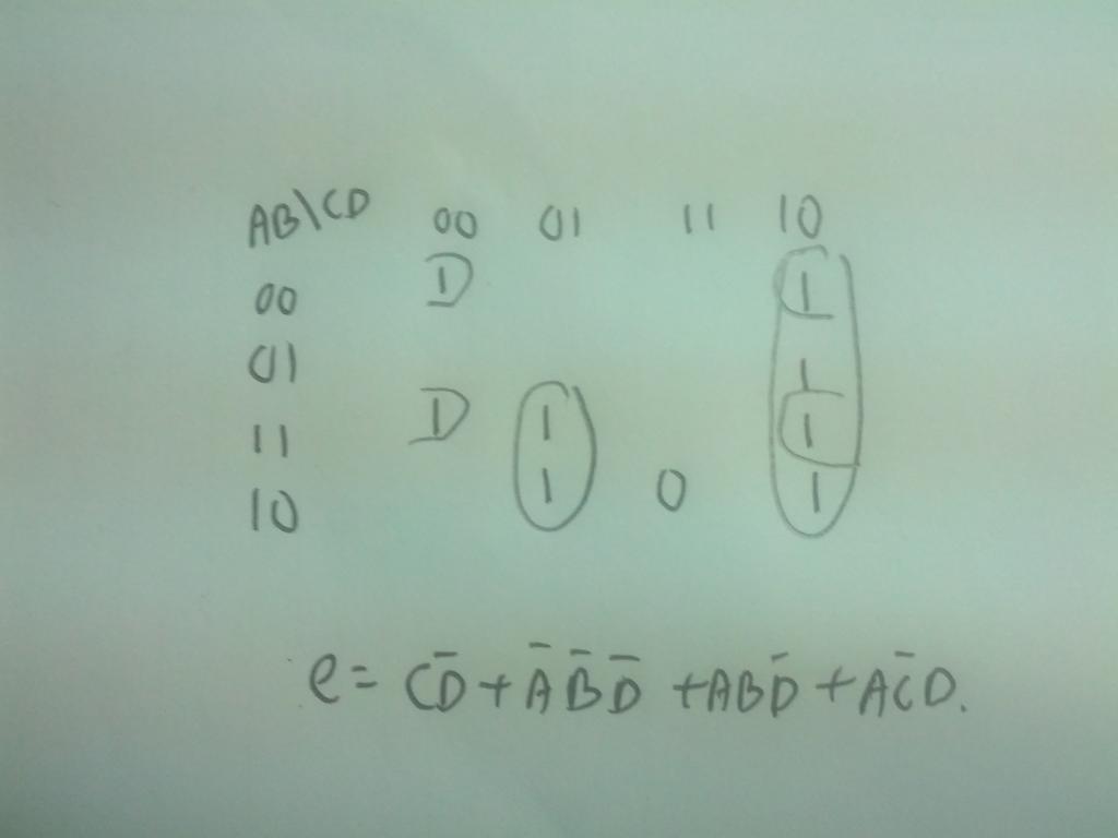
In this case the K-map is incomplete. You have 4 input variables which makes a total of 16 possible combinations. Only 9 of these combinations are valid. These are the fields that have either a 1 or a 0 in the map.
There are 7 invalid or better said unused input combinations. Since these combinations are never expected during operation of your circuit, you can assign a 1 or a 0 voluntarily to the output variable for these fields. Whatever you put in these fileds is not relevant for the used input combinations.
This you can use to optimize the map and thus to minimize the boolean equations. Look again at my colored map. See the third column from the left where AB=11. you have only one entry there: e=0 in the bottom row. The fields above are empty. Now insert 0 in the three empty fields in column 3. Now you have 4*0 in this column. Since the column is uniquely identified by A*B=1 (which is A AND B) the state of the variables C and D is irrelevant. For any combination of C and D the output e=0 is valiod as long A*B=1.
But A*B gives a logical 1. You need e=0. This is the inverse of 1 and so you have to add a negation: NOT(A*B)=0 (this is the same as A*B=1 - test it).
Therefore the minimized equation is e=NOT(A*B)=NOT(A AND B) = A NAND B

A more detailed explanation can be found here or here.
 

Laplace

Apr 4, 2010
1,252
Joined
Apr 4, 2010
Messages
1,252
Here are worksheets for the truth table and the K-map. In the K-map note that the olive-colored squares are required by the truth table, and the white squares are don't-care conditions. The blue squares are don't-cares which have been assigned a value for optimizing the minimization. One possible minimization is shown for segment 'a'. The minimization of segments 'b' through 'g' are left as an exercise for the reader.
 

Attachments

  • Karnaugh-Map.pdf
    70.9 KB · Views: 232
  • Truth-Table.pdf
    77.8 KB · Views: 119

vick5821

Jan 22, 2012
700
Joined
Jan 22, 2012
Messages
700
But I wonder how to get such a simple equation for segment e as A NAND B ?
 

Harald Kapp

Moderator
Moderator
Nov 17, 2011
13,725
Joined
Nov 17, 2011
Messages
13,725
I think I explained this rather detailed in my last post. What exactly is it that I didn't manage to make clear? If you can pinpoint the problem I can try to explain it differently.
 

(*steve*)

¡sǝpodᴉʇuɐ ǝɥʇ ɹɐǝɥd
Moderator
Jan 21, 2010
25,510
Joined
Jan 21, 2010
Messages
25,510
vick5821, in your case it is C NAND D

If you have a look at your diagram, ignoring the blank spaces (in which you can put any value you like) the values for A and B are simply not relevant.

Everything in the CD columns 00, 01, and 10 could be filled with 1's. Everything in the 11 column could be filled with zeros.

By simple inspection, the gate that only has a 0 output when both of the inputs are 1 is the NAND gate.
 

Laplace

Apr 4, 2010
1,252
Joined
Apr 4, 2010
Messages
1,252
I have added segment 'e' to the worksheet. Note that the blue squares were assigned the don't-care value of '0' to optimize the minimization since in this case we are minimizing the zeroes rather than the ones. This also means that the final result must be negated so the W AND X becomes W NAND X. The nice thing about using K-maps is that you don't really need to understand Boolean logic to get the right answer, you just follow the Karnaugh minimization rules and you get the right answer every time.
 

Attachments

  • Karnaugh-Map.pdf
    71.6 KB · Views: 148
Top