Maker Pro
Maker Pro

Simple NPN transistor circuit help

Mustwin351

Apr 10, 2013
49
Joined
Apr 10, 2013
Messages
49
Trying to use an NPN transistor as a switch but so far have had no luck.

Are there are any problems in the layout of my circuit?
 

Attachments

  • image.jpg
    image.jpg
    97.1 KB · Views: 271

KrisBlueNZ

Sadly passed away in 2015
Nov 28, 2011
8,393
Joined
Nov 28, 2011
Messages
8,393
Yes. Your battery is connected round the wrong way. Neither the transistor nor the LEDs will conduct with that polarity supply.

Also your LED symbols are missing the arrows. That means they won't emit any light :)
 

Mustwin351

Apr 10, 2013
49
Joined
Apr 10, 2013
Messages
49
Ok. I redid my circuit, tested and still nothing.

I even added arrows to my leds and it still won't light!

I thought on and NPN transistor you had the positive lead going to the base and the collector and the negative going to the emitter. Like in this image.
 

Attachments

  • image.jpg
    image.jpg
    7.6 KB · Views: 201

KrisBlueNZ

Sadly passed away in 2015
Nov 28, 2011
8,393
Joined
Nov 28, 2011
Messages
8,393
That circuit in post #4 will work. That is a PNP transistor in that diagram.
 

davenn

Moderator
Sep 5, 2009
14,260
Joined
Sep 5, 2009
Messages
14,260
....but I'm thinking with my transistor being an NPN it will not work because of my "flicker" led having to connect to the Positive base of the transistor. Is my thinking correct?

what transistor do you really have ?
you have shown 2 different circuits one using a NPN in post #3 and in post #4 a PNP

you are confusing us and yourself ;)

cheers
Dave
 

KrisBlueNZ

Sadly passed away in 2015
Nov 28, 2011
8,393
Joined
Nov 28, 2011
Messages
8,393
Yes, try to figure out exactly what you have.

You can change a circuit from using a PNP to using an NPN, or vice versa, by reversing the direction of all polarised components (the power supply, all diodes, and any polarised capacitors).
 

Harald Kapp

Moderator
Moderator
Nov 17, 2011
13,722
Joined
Nov 17, 2011
Messages
13,722
The circuit you linked is almost the same as in your post #4 and should work with the transistor you used there (PNP).
 

Mustwin351

Apr 10, 2013
49
Joined
Apr 10, 2013
Messages
49
The hand drawn sketches are my own and my transistor is specifically an NPN model # 2n2222a.

I have my "flicker" led in the correct orientation as well and have confirmed this with the diode test on my multimeter.

My voltage comes to 4.67 volts and I have a 100 ohm resistor to limit the current for the led.

Why my flicker led won't light is baffling me.
 
Last edited:

KrisBlueNZ

Sadly passed away in 2015
Nov 28, 2011
8,393
Joined
Nov 28, 2011
Messages
8,393
Make sure your circuit matches this one exactly (apart from the 2 ohm current limiting resistor).

flickering led.png
 

Arouse1973

Adam
Dec 18, 2013
5,178
Joined
Dec 18, 2013
Messages
5,178
Yes. Your battery is connected round the wrong way. Neither the transistor nor the LEDs will conduct with that polarity supply.

Also your LED symbols are missing the arrows. That means they won't emit any light :)

Maybe they are white LED's you wouldn't see the light arrows from them on white paper :)
 

Mustwin351

Apr 10, 2013
49
Joined
Apr 10, 2013
Messages
49
Ok I got it working....well partly...sorry it took me a while.

The "flicker" led won't light (not that it's really a concern but it should be), and my other 2 leds are lighting but very dimly and are not flickering like they should.

I've tried biasing the gate of the transistor without the flicker led and just used a ?????????

ohm resistor but I get the same effect (other two leds dimly lit)

My supply voltage is exactly 4.67.
My resistor for the pair of leds is 25 ohms.

Strangely though my multimeter says I am dropping 4v across the leds so I don't know why they would be dim. My transistor should be sourcing enough current and be fully saturated. Also I have the same 4v wether I'm reading across the two leds or the two leds and resistor.

It also seems odd that across my flicker led and resistor used to bias the transistor I am only reading .5 volts. I would think I should get the full voltage drop of my source voltage. (4.67v)
 

KrisBlueNZ

Sadly passed away in 2015
Nov 28, 2011
8,393
Joined
Nov 28, 2011
Messages
8,393
LEDs require a certain amount of voltage across them before current starts to flow. Have a look at a typical VF vs. IF graph from a data sheet:
LED IF vs. VF.png
This graph shows how the voltage across the LED is related to the current that will flow through the LED. The LED brightness is roughly proportional to the current.

If your circuit can't provide enough voltage to cause the current through the LED to be what you want, then the current will be lower than what you want, and the LED will be dimmer than you want.

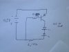
In your case, you have a 4.5V battery, and a transistor that will drop, say, 0.1V when conducting. That leaves about 4.4V across two LEDs in series. Voltages in series add together, so you will have about 2.2V across each LED. According to that graph, the LED current can't be more than about 2 mA.

These numbers, and the graph, are not exactly the same as your circuit, but they illustrate the point. And the point is that you need a higher battery voltage.

For more information, see Steve's tutorial at https://www.electronicspoint.com/resources/got-a-question-about-driving-leds.5/
 
Last edited:

Mustwin351

Apr 10, 2013
49
Joined
Apr 10, 2013
Messages
49
Thanks kris. According to the specs on my leds they each require only 2v a piece. I will try a higher voltage and see what happens.

I confirmed I am using the yellow ones too
 

Attachments

  • image.jpg
    image.jpg
    141 KB · Views: 147
Top